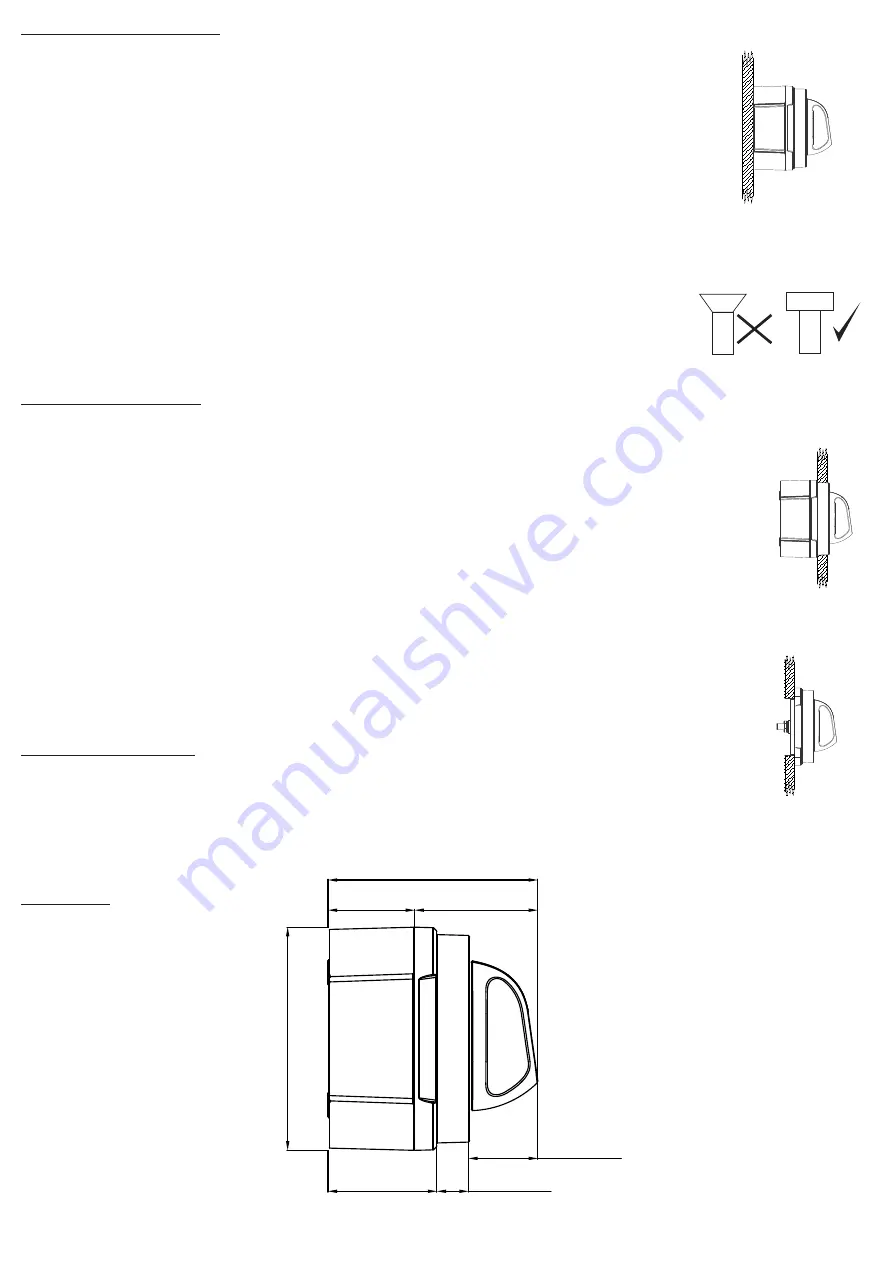
Panel Mount Instructions
1. Choose mounting location
2. Ensure positive leads are removed from battery banks
3. Use the mounting template (shown on rear page) to mark hole positions
4. Drill four machine screw holes and the 92mm (or 3 5/8”) hole for the switch body.
5. Front panel mounting only: either recess for the four clipping features (see template)
or cut/file off these features from the battery switch plate
6. Mount switch to panel using M6 (or ¼”) machine screws
– note: use either pan or cheesehead screws only
7. Connect cables to studs ensuring that batteries and loads are correctly fitted
8. Check that spring washers are fitted beneath nuts
9. Tighten the stud nuts to 13.5 Nm (10 lbf)
10. Tighten the AFD stud nuts to 2 Nm (1.5 lbf)
11. Rear panel mounting only: back plate and side panels can also be clipped to the switch
for cable protection/insulation
12. Ensure cables are secured to ISO/ABYC standards, and that cables are supported so they are not
placing strain on the battery switch studs (see diagram)
13. With switch in “OFF” position connect battery positive leads at battery
14. Check switch operation (as below)
Check switch operation:
a. Loads have no voltage in “OFF” position and AFD contacts are open
b. Loads have voltage in “1 ON” position and the AFD contacts are closed
c. Load share voltage in “2 ON” position and AFD contacts are closed
d. Loads have voltage in 1&2 positions and AFD contact are closed
SURFACE
MOUNT
REAR
PANEL
MOUNT
FRONT
PANEL
MOUNT
SURFACE
MOUNT
REAR
PANEL
MOUNT
FRONT
PANEL
MOUNT
SURFACE
MOUNT
REAR
PANEL
MOUNT
FRONT
PANEL
MOUNT
Surface Mount Instructions
1. Choose mounting location on a flat surface close to the batteries
2. Select panhead (or similar) screws for mounting - use either M5 or 10g imperial
(not included)
3. Knock or drill out plastic skin from screw holes in backplate
4. Select panhead (or similar) machine screws and nuts to secure switch to backplate -
use either M6 x 40mm or 0.25” x 1.5” (not included). Alternatively longer screws
should be used if bolting all the way through the bulkhead/surface
5. Place nuts for machine screws into nut recesses, then screw backplate into position
6. Connect cables to studs ensuring that batteries and loads are correctly fitted
7. Check that spring washers are fitted beneath nuts
8. Tighten the stud nuts to 13.5 Nm (10 lbf)
9. Tighten the AFD stud nuts to 2 Nm (1.5 lbf)
10. Slot the side panel(s) into the backplate as required
11. Clip battery switch and cable assembly into backplate
12. Secure switch in place with machine screws, engaging into nuts under backplate
13. Ensure cables are secured to ISO/ABYC standards, and that cables are supported so
they are not placing unnecessary strain on the battery switch studs (see diagram)
14. With switch in “OFF” position connect battery positive leads at battery
15. Check switch operation (as per below)
TO
RQ
UE
TORQUE
Panhead
Cheesehead
Sockethead
www.bepmarine.com | www.mastervolt.com | www.marinco.com
Mounting Template
Surface Mount Screw Holes
For Backplate
55.0 [2.17]
55.0 [2.17]
76.2 [3.00]
76.2 [3.00]
5.0 [0.20]
6.4 [0.25]
92.0 [3.62]
Use 3
5
8
"
holesaw
47.7 [1.88]
13.9 [0.55]
30.4 [1.20]
97.8 [3.85]
91.9 [3.62]
38.0 [1.50]
53.9 [2.12]
Clipping feature:
• Either remove clipping
features or recess panel
when front panel mounting
Dimensions:


