background image


These instructions help you to use our product 
properly, safely and economically. In the following 
text, our berbel island extractor hood BIH 60 CB 
product is briefly referred to as device. 


These instructions are intended for the following 
persons:  


Persons who use the device 


Persons who clean the device 


Persons who dispose of the device. 


Each of these persons must have read and 
understood the contents of these instructions. 

Compliance with these instructions helps to avoid 
dangers and to increase the reliability and service 
life of the device. 


Structural features in the text 


Defined structural features are assigned to the 
elements contained in these instructions. A 
distinction can therefore be easily made between 
the following elements: 

Normal text 

Cross references 


Lists or  


¾


Action steps. 


 Tips contain special information on the 

economical use of the device. 


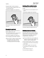
Structural features in illustrations 


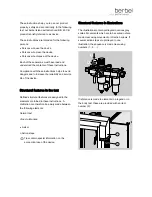
The illustrations contain portrayals in various grey 
scales. Movements which are to be carried out are 
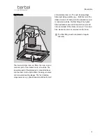
made clear using movement or direction arrows. If 
several action steps are portrayed in one 
illustration, the sequence is made clear using 
numbers (1., 2., ...): 


If reference is made to elements in a legend or in 
the body text, these are provided with an item 
number (2): 

2

1


Summary of Contents for BIH 60 CB

Page 1: ...berbel Island Hood BIH 60 CB Operating Instructions 10 2009 English version of original German instructions ...

Page 2: ...e of the device Structural features in the text Defined structural features are assigned to the elements contained in these instructions A distinction can therefore be easily made between the following elements Normal text Cross references Lists or Action steps Tips contain special information on the economical use of the device Structural features in illustrations The illustrations contain portra...

Page 3: ...lation function 13 Changing the output level 14 Switching off the ventilation function 14 Switching on the run on function 14 Switching the lighting on and off 15 Cleaning 17 Cleaning intervals 17 Cleaning in the case of normal soiling 17 Cleaning in the case of severe soiling 18 Cleaning surfaces 21 Cleaning the rotary knob 22 Maintenance 23 Maintaining the device 23 Maintaining the lighting 23 R...

Page 4: ...onversions or modifications without the approval of berbel Ablufttechnik GmbH are impermissible Never bridge or bypass the protective facilities available on the device Basic safety instructions This section contains basic safety instructions for handling the device Additional safety instructions which affect certain actions and procedures can be found in the relevant chapters Heed all of the safe...

Page 5: ... device to dripping or splashing water Never place objects filled with fluids such as e g vases on the device Keep the device dry If fluid nevertheless enters the device Immediately shut off the current supply by removing the fuse Make sure that the device s current supply cannot be unintentionally reactivated E g designate a person to prevent the fuse from being switched on Allow the device to dr...

Page 6: ...ountry are observed Ensure an adequate fresh air supply in the dwelling Do not allow children to play with film or other parts of the packaging Store film or other parts of the packaging in a location which is inaccessible to children Preventing the risk of collapse The necessary wall passage must be created by a specialist company Wall passages influence the building s statics Improperly created ...

Page 7: ...Safety 7 Structural features of notices regarding material or environmental damage ATTENTION These notices warn of a situation which leads to material or environmental damage ...

Page 8: ...m air into the room Cleaning is carried out in several cleaning stages The first cleaning stage removes e g grease and air particles from the intaken room air The next cleaning stage filters light flying particles e g fluff from the intaken room air The filter filling in the recirculating air filter neutralises existing odour contents The odour free cleaned room air is returned into the room The f...

Page 9: ...leaning stage removes e g grease and air particles from all of the intaken room air The next cleaning stage filters light flying particles e g fluff from all of the intaken room air Whilst part of the cleaned room air is conducted outside the filter filling in the hybrid filter neutralises odour contents which are present in the remainder of the intaken room air This odour free cleaned room air is...

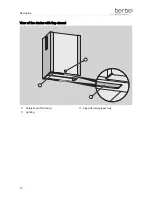
Page 10: ...Description 10 View of the device with flap closed 1 2 3 Rotary knob ThinCoder Flap with lower grease tray Lighting ...

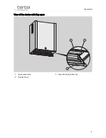
Page 11: ...Description 11 View of the device with flap open 1 2 3 Upper grease tray Flap with lower grease tray Capillar Trap ...

Page 12: ...from the left 3 4 7 6 2 1 5 Lock type mountings for the chimney panel Optional Recirculating air filter or hybrid filter Lower brackets for the chimney panel Optional Ventilation slits Rotary knob ThinCoder Chimney panel Extractor hood ...

Page 13: ...tion function WARNING Danger of burning due to flambéing beneath the device Naked flames may e g cause burns on the skin Do not flambé beneath the device ATTENTION Fire hazard due to flambéing beneath the device Naked flames may e g damage neighbouring cupboards Do not flambé beneath the device Replace the filter s filling if you switch the device on and determine an unpleasant odour See Cleaning ...

Page 14: ...ventilation function Proceed as follows to switch off the ventilation function Turn the rotary knob counter clockwise to the 0 position The rotary knob engages at each output level The device switches the ventilation function off Switching on the run on function The device is equipped with a run on function When this function is used the device continues to operate at the current output level for ...

Page 15: ... The rotary knob engages at each output level Turn the rotary knob to level 1 Turn the rotary knob to level 0 The device operates at the output level last selected and switches off after ten minutes Switching the lighting on and off In order to illuminate the cooker top the device is equipped with energy saving LED lighting The lighting can be used independently from the fan Switching on the light...

Page 16: ...Operation 16 Switching off the lighting Proceed as follows to switch off the lighting Press gently on the rotary knob with one finger The lighting is switched off ...

Page 17: ...ime after cooking See Cleaning in the case of normal soiling on page 17 Daily or extensive use After 3 weeks at the latest See Cleaning in the case of severe soiling on page 18 Cleaning in the case of normal soiling The device is designed in such a way that the foreign particles contained in the intaken room air are collected on the grease trays Proceed as follows to clean the device in the case o...

Page 18: ...ere soiling Removing the lower grease tray Switch the device off Open the flap by pulling it downwards at the rounded edge The flap is open Use a soft moist cloth or paper for cleaning Wipe the parts off Grip the grease tray which is folded down vertically at the sides using both hands Raise the lower grease tray approx 2 cm 1 Release the lower grease tray by pulling it forwards 2 1 2 Remove the l...

Page 19: ... guide pins Lower the front side of the grease tray at an incline 1 Pull the grease tray downwards out of the device 2 1 2 Cleaning parts ATTENTION Damage to the flap with the lower grease tray due to incorrect cleaning Never clean the flap with the lower grease tray in the dishwasher Clean the lower grease tray e g with a moist cloth Clean the lower grease tray e g with a moist cloth Clean the re...

Page 20: ...grease tray horizontally 2 2 1 Secure the grease tray by pressing it upwards into the device until the locks audibly engage Make sure that the upper grease tray is inserted correctly The upper grease tray is correctly inserted when it is suspended horizontally in the device and both locks have audibly engaged and are flush with the surface CLICK Installing the Capillar Trap Make sure that the Capi...

Page 21: ...ase tray by pressing it backwards into the device 1 Lower the grease tray Make sure that the grease tray is inserted correctly The grease tray is correctly inserted when both flap guide grooves are inserted into the device s guide pins The flap can be moved 2 1 2 Closing the lower flap Close the flap by pressing it up until both retaining magnets audibly make contact Cleaning surfaces ATTENTION Da...

Page 22: ...TION Damage to the rotary knob in the case of incorrect alignment Turn the rotary knob to the correct installation position The rotary knob must be placed onto an axle This round axle is milled at one edge The rotary knob can therefore only be placed onto the axle in one position Make sure that the installation position is correct Position the rotary knob in the correct installation position on th...

Page 23: ...ittle or occasional use In the case of odours in the outgoing air after 24 months at the latest Daily or extensive use In the case of odours in the outgoing air after 12 months at the latest WARNING Risk of falling when replacing filter Use a stable stepladder WARNING Risk of injury due to falling parts Make sure that nobody is standing beneath the working area during work ATTENTION Damage due to ...

Page 24: ... 2 from below 1 2 Position yourself in front of the left hand side of the device Grip the chimney panel in the upper area of the device using both hands Pull the upper area of the chimney panel 1 towards yourself Lift the chimney panel upwards out of the lock type mountings hooks 2 1 2 ...

Page 25: ...el vertically until it is free 2 1 1 Place the chimney panel down securely in a location outside of the working area Removing the hybrid filter Proceed as follows to replace the filter filling Remove the outgoing air line from the sleeve ...

Page 26: ...ll the filter out upwards using the folding handle Replacing the filter filling Replace the filter filling Replacement of the filter filling is described separately in the operating instructions for the filter filling Installing the filter To ensure that the filter is installed correctly an approx two centimetre high guide aid is installed on the seat of the filter ...

Page 27: ...t the filter is inserted correctly The filter is installed correctly If the filter is not installed correctly proceed as follows Remove the filter Position the filter again Hybrid mode only Position the sleeve on the filter Slide the outgoing air line into the sleeve Mask the transition between the outgoing air line and the guide aid with sealing tape ...

Page 28: ...ngage in the square centring apertures on the upper edge of the chimney panel and hook the chimney panel in Retaining magnets secure the lock type mountings in the final position Whilst inserting the chimney panel the lock type mountings must be folded out If the lock type mountings are folded in the chimney panel is not mounted Fold open the two lock type mountings 1 by pressing against the sides...

Page 29: ... panel onto the device 2 until the lock type mountings retaining magnets audibly come into contact 1 2 1 The lock type mountings engage in the square centring apertures on the upper edge of the chimney panel and hook the chimney panel in Retaining magnets secure the lock type mountings in the final position Make sure that the upper area of the chimney panel is held by both lock type mountings 1 1 ...

Page 30: ...ying malfunctions 30 Rectifying malfunctions DANGER Fatal electric shock due to improperly carried out repairs Make sure that repairs are carried out exclusively by the manufacturer or authorised specialists ...

Page 31: ...nd the window is closed Open the window Lighting does not function The light strip is defective If the lighting does not function contact your specialist berbel dealer The recirculating air filter filling is spent Replace the recirculating air filter filling See Replacing the filter filling hybrid and recirculating air filters on page 23 Increased noise development during operation Odour formation...

Page 32: ...o environmental compatibility aspects and are manufactured from recyclable materials After use the packaging materials can be recycled Valuable raw materials can therefore be saved The exterior packaging consists of cardboard The filler material and the inserts consist of cardboard or polystyrene The protective films and bags consist of polyethylene PE Dispose of the packaging according to materia...

Page 33: ...adheres and test symbols Island Hood BIH 60 CB Width 600 mm Depth 430 mm Height 800 mm Max fan output free blowing 1 fan with 750 m h Weight air extraction mode Approx 49 kg Weight recirculated air mode Approx 54 kg Power consumption 215 W output level 4 LED bulb 24 V 12 W The device has been manufactured under adherence to the regulations of VDE 60335 2 31 and complies with the following directiv...

Page 34: ...cturer If you have any questions which are not answered by these instructions contact berbel Ablufttechnik GmbH Sandkampstraße 100 D 48432 Rheine Telephone 49 0 800 56 06 06 0 Fax 49 0 800 56 06 06 1 Internet www berbel de Free from the German land line ...

Page 35: ...35 KONTECXT GmbH Technische Dokumentation D 45145 Essen www technische dokumentation de Printed in Germany ...

Reviews: