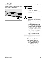
Installing the device
46
Installation instructions
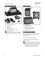
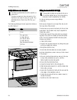
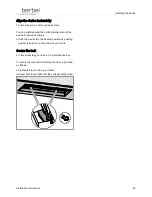
Safety distances are observed
The following illustrations show the operation or
dimensions.
The devices used are shown as symbols. The
illustrations are meant to serve as a guide. The
illustrated device shapes may differ from your
device.
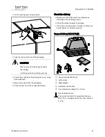
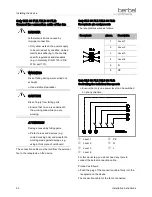
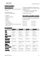
The following statutory minimum separation distances
must be observed:
Description
Size
Y
0 mm
X
For gas hobs:
at least 650 mm.
For electric hobs:
at least 350 mm.
Recommended distance:
550 mm
Fitting the bracket BLB 60 FL(E)
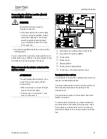
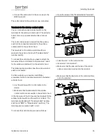
The supplied brackets are suitable for 16 mm to
22 mm thick cabinet bases. The corresponding
dimension must be adjusted by the installer.
For this work step you need a large Phillips
screwdriver.
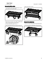
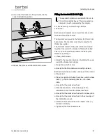
Both removed brackets are screwed from above onto
the base plate of the cabinet.
The brackets are pre-set in the factory for 16 mm thick
base plates. The brackets must only be adjusted for
thicker base plates.
The brackets consist of two parts which are screwed
together. One part of the bracket is fitted with slotted
holes. You can adjust the bracket to the base plate
thickness by sliding it.
Ø
Loosen both screws.
Ø
Adjust to the required dimension by sliding the upper
part of the bracket accordingly.
Ø
Re-tighten up both screws.
Ø
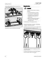
Ensure that both brackets are correctly adjusted.
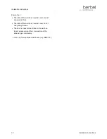
Both bent metal tabs are above and point to the interior
of the cabinet.
Ø
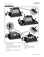
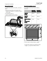
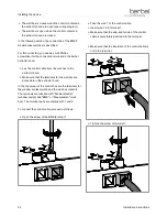
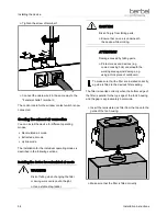
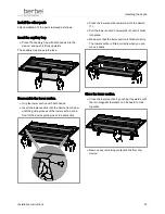
Place the right-hand bracket from above on the rear
corner of the installation cut-out (1.) until the
fastening tabs lie on the base plate.
Ø
Ensure that the bracket lies flush.
Ø
Screw the bracket flush to the side edge (2.).
Ø
Slide the bracket rearwards (3.) until the bracket lies
flush to the rear edge.
Ø
Ensure that the bracket is flush with the rear and the
side edges of the installation cut-out.
Ø
Fasten the bracket with the cross-head screws (4.)
included in delivery.
Ø
Tighten up the cross-head screws.
Summary of Contents for BLB 60 FL
Page 63: ...Contact 63 ...

