18
Installation
6004977_a – 28.02.2020
3.5.7
Connect accessories
Available accessories are connected depending on the
installation situation:
y
Wall box
Observe the instructions for the accessories.
12 V DC
4
BMK-F
BMK-F
2
3
1
C
A
B
B
D
E
12 V DC
E
D
C
12 V DC
BMK3
BMK4
BMK2
BMK1
ST3
+
+
–
–
+
+
–
–
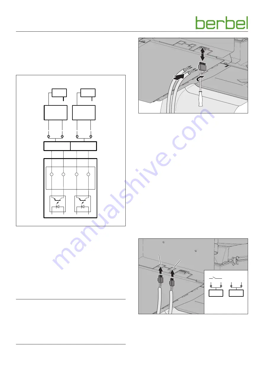
A Control box
y
BMK1: Wall sleeve contact, optocoupler collector,
max. 12 mA / 12 V DC, safe galvanic separated
y
BMK2: Wall box contact, optocoupler emitter,
max. 12 mA / 12 V DC, safe galvanically isolated
B Terminal “BMK-F” for the wall box connection
C Control line from the wall box
D Wall box
E Wall box mains adapter
Connection takes place via a 4-pole connection plug under
the service cover.
D
ATTENTION!
Risk of damage through incorrect connection!
A mix-up of the control wires can result in damage to the
electronics.
☞
Be careful not to mix up connections when connecting
the control wires: Core 1 on terminal 1, core 2 on
terminal 2.
1.
2.
Wall box
☞
Connect the wall box as follows:
y
Core 1 on terminal 1
y
Core 2 on terminal 2
y
The wall box is closed when the control contacts are
open.
y
The wall box is open when the control contacts are
closed.
Window contact switches BKF DL can be connected via an
auxiliary control (optional).
☞
Please consult your dealer or customer services.
3.5.8
Connect light source (optional)
The device enables the connection of an external light source,
which can be controlled via the device.
D
“4.3.11 Light function (optional)” (page 27).
Connection takes place via the 2-pole connection plug under
the service cover.
X7
X10
1-10 V DC
out
230 V AC
2
X7
1
2
X10
1
+
–
X7
max. 230 V AC / 6 A – potential-free contact
connection (power max. 1380 W)
X10
1-10 V DC – connection only for light sources with
dimmable inputs
Summary of Contents for Downline BKF 83 DL-A
Page 40: ...6004977_a 28 02 2020 ...


