background image

41

Disposal

6006047_0 – 02.09.2021

EN

8. 

Disposal

8.1 

Dispose of packaging


D

ATTENTION!

Risk of environmental damage due to improper disposal 

of the packaging!


Do not put the packaging into the normal household 
waste.


Take the packaging for environmentally friendly and 
proper recycling.

The packaging provides protection from transport damage.
Only the original packaging guarantees sufficient protection 
during transportation.


Store the packaging in a location which is inaccessible to 
children.

The packaging materials have been selected from an 
environmentally friendly perspective and are made from 
re-usable materials. The packaging materials can be returned 
to the raw materials cycle after use. This saves valuable raw 
materials.


y

The outer packaging is made from cardboard.


y

The filling material and the insets are made from 
cardboard or polythene (PE).


y

The protective film and bags are made from 
polythene (PE).


Dispose of the packaging in an environmentally friendly 
manner, separated by materials.

8.2 

Dispose of the device


D

ATTENTION!

Risk of environmental damage due to improper disposal 

of the device!

The device is subject to the European Directive 2012/19/EU 
and should not be disposed of with household waste.


Do not put the device into the normal household waste 
at the end of its service life.


Enquire about the disposal options or environmentally 
friendly and proper recycling opportunities with your 
municipal or regional authorities.


Dispose of the device in accordance with the legal 
provisions via a professional disposal centre or at your 
local disposal facility.


WEEE-Reg.-Nr. 59614689

Summary of Contents for Downline Infinity BKA 90 DLI

Page 1: ...EN Hob extractor fan Downline Infinity EN Operating and installation instructions for the models BKA 90 DLI 6006047_0 ...

Page 2: ...uld result in serious injuries or death D CAUTION Notes with the word CAUTION warn of a situation that could result in minor injuries D ATTENTION Notes with the word ATTENTION warn of a situation that could result in damage to property or to the environment Symbol clarification text Handling requirement y Listing D Reference to another point in this document Reference to other documents that shoul...

Page 3: ...0 3 5 9 Establish electrical power supply 21 3 5 10 Check and carry out commissioning 21 4 Operation 22 4 1 Safety instructions for operation 22 4 2 Cooking with induction 23 4 3 Control panel 24 4 4 General operation of the device 26 4 5 Operation of the hob 27 4 5 1 Extraction operating mode 27 4 5 2 Grill function 27 4 5 3 Head chef function 28 4 5 4 Automatic pot recognition function 28 4 5 5 ...

Page 4: ... qualified specialist personnel Requirements on qualified specialist personnel y Knowledge of the regulations on safety at work y Knowledge of fastening systems y Basic knowledge of ventilation systems y Experienced in using electrical and mechanical tools y Ability to read technical drawings y Knowledge of this manual Operation cleaning and maintenance by the user Requirements for the user y Know...

Page 5: ...s y In potentially explosive atmospheres y If the device or individual components are damaged y In the event of unauthorised alterations or changes to the device y If liquid has penetrated the device y When heavily soiled y For children under 8 years old and persons who would not be able to properly assess the hazards associated with handling the device The manufacturer accepts no liability for da...

Page 6: ...ted air mode it is necessary to use the run on function so that the device can remove the remaining odours Using the run on function increases the life of the filter filling The filter filling must be replaced at regular intervals In the case of devices with recirculated air filter permalyt as an extension for permanent odour retention there is no need to renew the filter filling 2 2 2 Extraction ...

Page 7: ...bon filter y Recirculating air kit DL BUR installation variant for recirculated air mode with recirculated air filter permalyt y Exhaust air kit DL installation variant for extracted air mode The instructions for installation variants with blow out grate kit must be observed 2 4 2 Accessory recirculating air kit DL BUF A B D C E F G H A Circulating air bend B 2x recirculated air fan BUF 150 DL wit...

Page 8: ...uct 1000 mm long E Height compensation plates thickness 0 5 1 0 1 5 2 0 mm F Mains cable with plug and cold device plug G 2x compression tape H 2x sealing strip I 2x fastening base 2 4 4 Accessory exhaust air kit DL C B A D E F G A 150 mm conduit bend 90 vertical B 150 mm elbow duct 352 mm long C 150 mm shallow duct 500 mm long D Height compensation plates thickness 0 5 1 0 1 5 2 0 mm E 2x fasteni...

Page 9: ... 240 mm 240 x 240 mm 240 x 240 mm Dimensions of internal cooking zone 154 x 154 mm 154 x 154 mm Min pot base diameter external cooking zone 70 mm 70 mm 160 mm 160 mm Min pot base diameter internal cooking zone 80 mm 80 mm Front left Rear left Rear right Front right Output 1 external cooking zone 2300W 2300W 2300W 2300W Output 1 internal cooking zone 1100W 1100W Boost output 1 external cooking zone...

Page 10: ...eres y With simultaneous use of a heating point which uses air from the room as its oxygen supply e g chimneys y A safety device is absolutely essential y The safety device must prevent gases being drawing to the room y It is essential to ensure that the negative pressure in the heating point installation room does not exceed 4 Pa y An approval for commissioning e g from a chimney sweep must be av...

Page 11: ...stallation of the necessary accessories y Window contact switch BKA DL y Wall box 3 4 Requirements for the exhaust air ducting only for extracted air mode D WARNING Fire hazard and asphyxiation hazard due to improper installation When using the exhaust air ducting with other devices or when connecting an active exhaust air channel e g chimney gases or smoke can be drawn into the room Make sure tha...

Page 12: ...with thick cardboard Ensure that the power supply is switched off and remains so Connect the power supply only when instructed to do so in the installation instructions The instructions for installation variants with blow out grate kit must be observed If accessories e g wall box window contact switch are required for the installation Observe the instructions for the accessories Ensure that the ac...

Page 13: ...mm Depth b 530 2 mm Work top Height z 10 mm Check the dimensions D 2 5 Technical data page 9 Ensure that the work top is suitable for the hob installation A B Check the spatial conditions for your installation variant A If necessary due to spatial conditions e g with large base cabinets shallow duct sections can be installed between the opening on the fan housing and the circulating air bend or co...

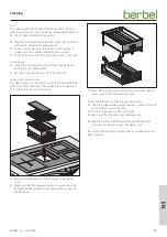
Page 14: ...ion of the device requires a great deal of physical exertion due to its size and weight If the device falls the device kitchen furnishings and other objects could be damaged Cover the working surface Keep the installation area clear The instructions for installation variants with a hob frame must be observed The following step is omitted 2 mm Remove the protective film from the sealing strip Adher...

Page 15: ...pecial paint silicone rubber or cast resin For the material used the worktop manufacturer s instructions must be followed Place the hob into the specified position in the lower cabinet from above Fit the separator insert in the opening of the hob Fit the intake grate on the separator insert Fit the Powermover on the intake grate ...

Page 16: ...air carrying components e g circulating air bend shallow duct sections must be sealed with sealing strip after they have been fit together Insert the circulating air bend in the connection on the fan housing Align the recirculated air filter with the flap device to the access side When doing so observe the specification on the device Adjust the recirculated air filter position 20 100 x 15 Adjust t...

Page 17: ...nstallation variants with blow out grate kit must be observed By trimming it is possible to align the shallow duct with the spacing between the connections y Between the fan s housing and circulating air bend with deep base cabinets y Between the circulating air bend and recirculated air filter with high base cabinets D 3 5 3 Check the dimensions page 13 For the following steps the adaptors of the...

Page 18: ...t Unscrew the screw on the side to lower the recirculated air filter x Cut the appropriate shallow duct sections The quantity and length must be adapted to the installation variant Insert the shallow duct sections in the circulating air bend Re adjust the recirculated air filter to the appropriate height Firmly tighten the screw on the side of the recirculated air filter The recirculated air filte...

Page 19: ...low duct sections The quantity and length must be adapted to the installation variant For the following steps the adaptors of the air carrying components e g conduit bend shallow duct sections must be sealed with sealing strip after they have been fit together Insert the conduit bend in the connection on the fan housing Insert the elbow duct in the conduit bend The routeing of the exhaust line tak...

Page 20: ... inserted A B A Jack socket for connection of wall box or control flap B Connection socket RJ45 BUS interface for connection with special accessories of the manufacturer Connection with a PC or other devices is not permitted Wall box y The wall box is closed when the control contacts are open y The wall box is open when the control contacts are closed Window contact switch y The fan of the device ...

Page 21: ...electricity supply after installation Recirculating air kit DL BUR Insert the cold appliance plug into the connection socket on the recirculated air filter Plug the mains plug into the socket After switching on the power supply the device is ready for operation 3 5 10 Check and carry out commissioning D ATTENTION Risk of disruptions due to moisture in the device If the device is moved from a cold ...

Page 22: ...ed as a result y Do not place metallic objects on the hob because they can become hot during use y Sharp and hard objects e g pot edges can damage the glass on the hob due to impact or falling y Do not use magnetic objects e g data carriers credit cards near the device The function of these objects can be impaired y If there is a drawer under the hob y Do not store flammable objects e g spray cans...

Page 23: ...ottoms because they are not suitable y Do not use magnetic objects e g data carriers credit cards near the device Because the device works with a magnetic field the function of these objects can be impaired Even if the device is working perfectly and the cookware is suitable for induction hobs the following noises may arise during cooking y Humming whistling buzzing clicking Possible causes y When...

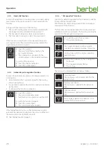
Page 24: ... cooking zone E Operation of the entire hob F Extraction operation G 4x 7 segment display H On Off button The control panel consists of sensor buttons Each button must be pressed to execute a specific action Execution of the action is confirmed by an acoustic signal and a corresponding display Function keys for the device in general ON OFF 4x 7 segment display Function keys for the entire hob Menu...

Page 25: ...nt down Cooking zone count up Automatic boost Simmer Boost Double boost Function keys for extraction 7 segment display of extraction Previous power level Next power level No function Filter filling indicator window contact switch Run on function The display only shows the buttons that are available or required for the active function Activated buttons illuminate brightly ...

Page 26: ...he cooking zone is selected with the corresponding 7 segment display or via the automatic pot recognition Touch the 7 segment display y The 7 segment display lights up brightly y Further entries only apply for the selected cooking zone Choose a power level by tapping or swiping the slider y The position of the slider is displayed in colour y The cooking zone is heated accordingly y The automatic e...

Page 27: ...l mode The setting of the fan power takes place manually The connection between the selection of the cooking zone level and fan power selection is severed Semi automatic mode When the hob is switched on and a cooking zone is activated the fan is also switched on automatically to power level 2 In further operation the connection between the selection of the cooking zone level and fan power is sever...

Page 28: ...e symbol y The symbol illuminates dimly y Automatic pot recognition is switched off To switch the function on again Touch the symbol again y The symbol illuminates brightly If the bridge function is in use the cookware may not be automatically detected e g because the size is insufficient or the material does not optimally conduct D 4 6 7 Bridge function page 31 4 5 5 Pot speed test function Funct...

Page 29: ...ime as follows y Tap the button 30 second steps y Hold the button one minute steps y The time starts to run 5 seconds after it is set 4 5 8 Pause function Function for interruption of a cooking process with saved settings Touch the symbol y The cooking process is interrupted y The adjusted values are saved To end the function Touch the pause and lock symbols at the same time y The adjusted values ...

Page 30: ... active To switch off the function Touch the symbol for 5 seconds 4 6 Operation of the cooking zones Additional functions are available via the cooking zones menu button Touch the cooking zone menu button for 1 second y The symbols of the functions are displayed D The functions are described in the respective sections y If no function has been selected the cooking zone menu switches off after 5 se...

Page 31: ...g level y The selected simmering level is displayed on the 7 segment display y The cooking zone is heated accordingly y In automatic mode the fan power is adjusted automatically Lowest level Medium level Highest level 4 6 5 Boost function Function for heating up the cooking zone quickly Touch the symbol to start the power level boost y The cooking zone is heated up y The output of the automatic ex...

Page 32: ... removing cooking fumes Move the Powermover in the direction of the side with the lowest proportion of cooking fumes The Powermover is magnetically held in the centre and at the sides During the cooking process switch to a power level that is appropriate for the intensity of the cooking vapours If the intensity of the cooking vapours does not subside switch to a higher power level Switch to the po...

Page 33: ...r a further 10 minutes at power setting after it has been switched off In recirculated air mode it is necessary to use the run on function so that the device can remove the remaining odours Using the run on function increases the life of the filter filling The filter filling must be replaced at regular intervals The device is switched on If the automatic run on function is activated Touch the butt...

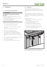
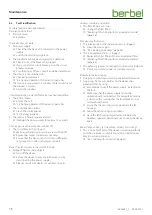
Page 34: ...2 Cleaning procedures If sugar plastic aluminium foil or similar materials come into contact with the hot hob these materials must be removed immediately Turn off the device Remove the materials while they are still hot There is a risk of burns because the hob is hot Before every cleaning Turn off the device Make sure that the hob and other parts that could be touched have cooled down D ATTENTION ...

Page 35: ...he device draws in dirt particles e g grease and oil particles with the air from the room The dirt particles are separated and collected in the separator insert Remove the Powermover intake grate and separator insert Make sure that the separator insert is not placed on the hob because the automatic pot recognition can switch the device on Press the buttons on the side to disconnect the upper or lo...

Page 36: ...d be touched may still be hot There is a risk of burning y Never open the fan housing y The recirculated air filter must be freely accessible 6 2 Maintenance Replacing filter filling with recirculated air mode Odours are trapped in the filter filling in the recirculated air filter The odour free cleaned room air is fed back into the room Recirculated air filters are maintenance free for up to two ...

Page 37: ...Unscrew the screws on the bottom of the filter cartridge Open the filter cartridge by removing the filter bottom Empty the filter completely Fill the filter with new charcoal up to the maximum level Screw the filter cartridge back in place Clean the filter from the outside e g through extraction with a vacuum cleaner Insert the filter cartridge in the filter housing Fold in the filter cartridge Lo...

Page 38: ... sharp objects Turn off the device Secure the device to prevent further use e g by disconnecting the power supply Please consult your dealer or customer services Odours occur during operation y The filter filling is used up Change the filter filling D Replacing filter filling with recirculated air mode page 36 Poor device performance y The intake grate or the separator insert is clogged Clean the ...

Page 39: ...ged Switch on the device again The display on the control panel shows E25 E26 E27 E28 y The hob has overheated y E25 front left cooking zone y E26 rear left cooking zone y E27 rear right cooking zone y E28 front right cooking zone Turn off the device Allow the device to cool down Switch on the device again The display on the control panel shows E30 y The air inlet of the fan is clogged Turn off th...

Page 40: ... furnishings and other objects could be damaged Keep the installation area clear Disconnect all poles of the power supply for the device If present Remove any accessory connection cables In extracted air mode Remove the exhaust air duct In recirculated air mode Remove the recirculated air filter Disconnect the connecting cable from the power supply Release the device fastening to the work top If p...

Page 41: ...is saves valuable raw materials y The outer packaging is made from cardboard y The filling material and the insets are made from cardboard or polythene PE y The protective film and bags are made from polythene PE Dispose of the packaging in an environmentally friendly manner separated by materials 8 2 Dispose of the device D ATTENTION Risk of environmental damage due to improper disposal of the de...

Page 42: ... air kit DL Annual energy consumption in kWh 45 7 Energy efficiency index EEI 43 7 EEI Hood Class A FDE Hood 34 1 FDE Hood Class A LE Hood LE Hood Class GFE Hood 92 3 92 3 92 3 GFE Hood Class B B B Flow rate in extracted air mode in m h Stage min max 200 600 Stage Power Intense 700 Flow rate in recirculated air mode in m h Stage min max 120 500 80 490 Stage Power Intense 580 580 Noise power level ...

Page 43: ...80 80 9 0 Mon to Thu 8 00 17 30 hrs and Fri 8 00 16 30 hrs Fax 49 0 5971 80 80 9 10 Internet www berbel de Email info berbel de Contact the manufacturer s customer support department There are several ways for you to contact our customer service Please select from the following options Telephone 49 0 5971 80 80 9 0 Mon to Thu 8 00 17 00 hrs and Fri 8 00 15 00 hrs Fax 49 0 5971 80 80 9 10 Email ser...

Page 44: ...6006047_0 02 09 2021 ...
Reviews: