19
Installation
6004067_a – 01.08.2018
EN
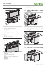
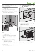
150 - 200
☞
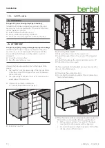
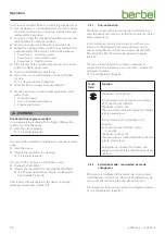
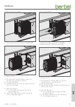
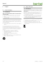
Switch the device on.
☞
Drive the device approx. 150 to 200 mm upwards.
☞
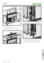
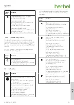
Align the upper trim frame with the water drip bowl at
the front.
☞
Slide the upper trim frame over the device onto the
prepared work top.
☞
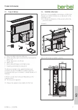
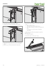
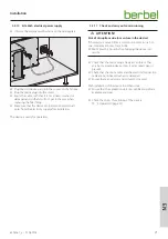
Make sure that the device can drive in or out without
touching the trim frame.
☞
Fully retract the device.
☞
Turn off the device.
☞
Disconnect the device from the power supply.
D
3.5.7
Install the hob
☞
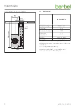
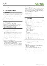
Mount the hob.
Observe the hob instructions.
☞
Check the hob seal (e.g. with silicone).
3.5.8
Connect accessories
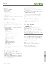
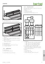
Depending on the installation situation, accessories may be
connected to the hood:
y
Wall box
y
Window contact switch
y
Under-pressure monitor
Observe the instructions for the accessories.
12 V DC
4
5
6
7
8
9
BMK-F
F-K
2
3
1
D
A
B
C
E
F
G
H
12 V DC
GND
X1
X1
X1
X1
X1
+
5 V
MFK
MFK
BMK2
BMK1
ST3
+
+
–
–
I
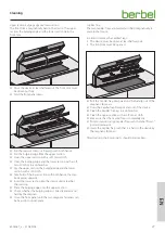
A Control box
y
BMK1: Wall sleeve contact, optocoupler collector,
max. 12 mA / 12 V DC, safe galvanic separated
y
BMK2: Wall sleeve contact, optocoupler emitter,
max. 12 mA / 12 V DC, safe galvanic separated
B Terminal “BMK-F” for the wall box connection
C Terminal “F-K” (multifunction contact) for the window
contact switch or under-pressure monitor connection
D Control line from the wall box
E Wall box
F Wall box power unit
G Window contact switch
H Control line from the window contact switch
Summary of Contents for Moveline BTH 100 ML
Page 35: ...35 6004067_a 01 08 2018 EN ...
Page 36: ...6004067_a 01 08 2018 ...


