34
Annex
6004067_a – 01.08.2018
9.2
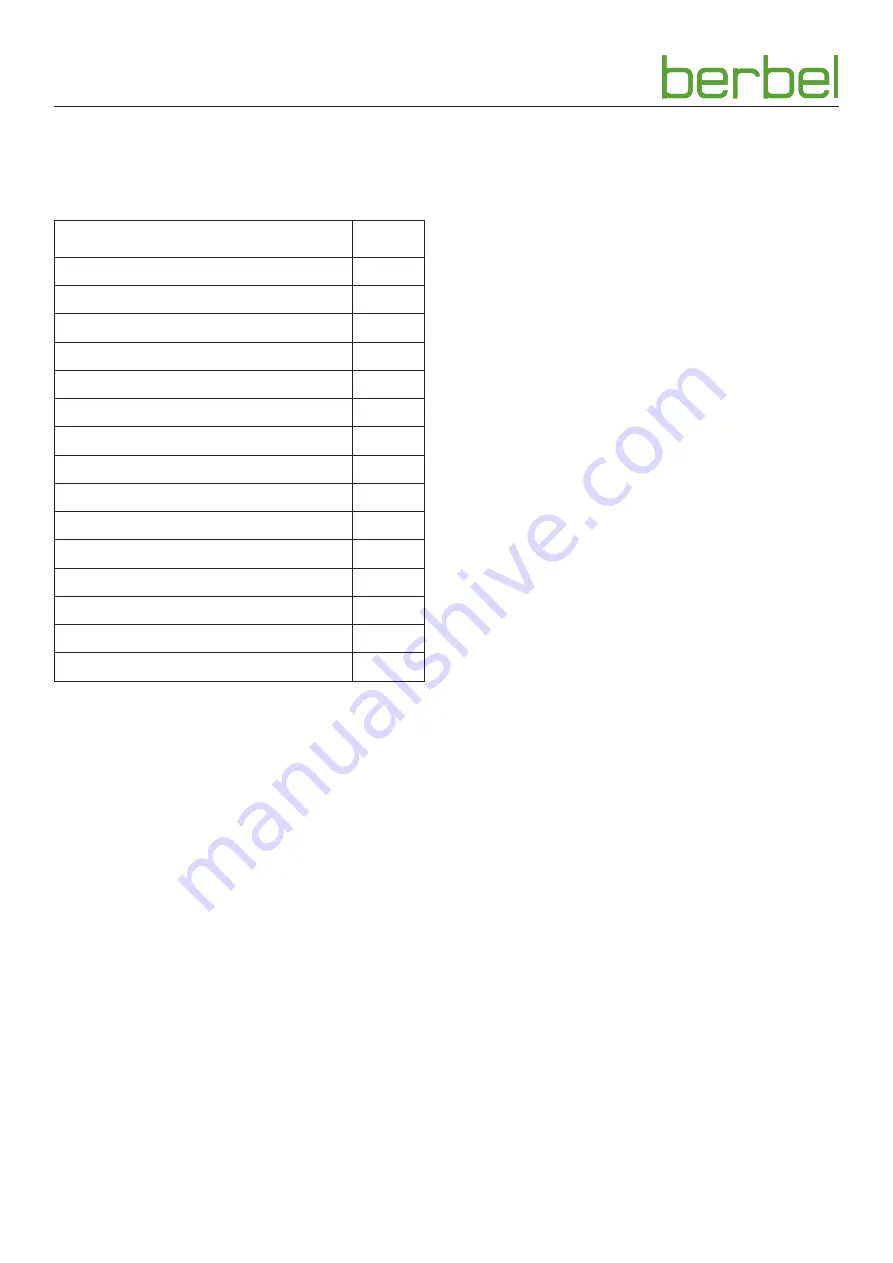
Accessories
When using accessories, the associated documentation
must be observed.
Article
no.
Recirculated air filter BUF 150 +
1003325
Hybrid filter BHF 150 +
1003607
Holding clamp (single)
2000658
Top-up pack berbel Pro Aktiv 150
1000875
Wall box BMK-F 150
1001330
Wall box BMK-Z 150
1001390
Radio window contact switch
1002916
Ventilation grill stainless steel, 2-part
6002271
Conversion to remote control BFB
1004767
Exhaust air set I round 150
1004729
Exhaust air set II flat 150
1004730
Exhaust air set III flat 150 double
1004731
Exhaust air set ECO I round 150
1004732
Exhaust air set ECO II flat 150
1004733
Exhaust air set ECO III flat 150 double
1004734
9.3
Contact
If you have any questions or suggestions, please select from
the following options:
Post:
berbel Ablufttechnik GmbH
Sandkampstraße 100
D-48432 Rheine
Tel:
+49 (0) 5971 80 80 9 - 0
Mon to Thu 08:00 – 17:30 hrs
and Fri 08:00 – 16:30 hrs
Fax:
+49 (0) 5971 80 80 9 - 10
Internet:
www.berbel.de
email:
info@berbel.de
Contact the manufacturer‘s customer support
department
There are several ways for you to contact our customer
service. Please select from the following options:
Tel:
+49 (0) 5971 80 80 9 - 660
Mon to Thu 08:00 – 17:30 hrs
and Fri 08:00 – 16:30 hrs
Fax:
+49 (0) 5971 80 80 9 - 10
email:
service@berbel.de
Summary of Contents for Moveline BTH 100 ML
Page 35: ...35 6004067_a 01 08 2018 EN ...
Page 36: ...6004067_a 01 08 2018 ...


