background image

20

Cleaning

6006244_0 – 30.05.2022


D

CAUTION!

Danger of injuries due to device edges!

When removing and replacing the lower section or the cross 
flow, fingers may become trapped and crushed.


Move the device parts slowly and carefully. 


D

ATTENTION!

Danger of damage due to falling parts!

The lower section and the Capillar Trap can fall down when 
being removed and damage the hob, the kitchen furnishings 
or other objects.


Hold the parts tightly when removing.


Protect the area below the device (e.g. using thick 
cardboard).

Lower section

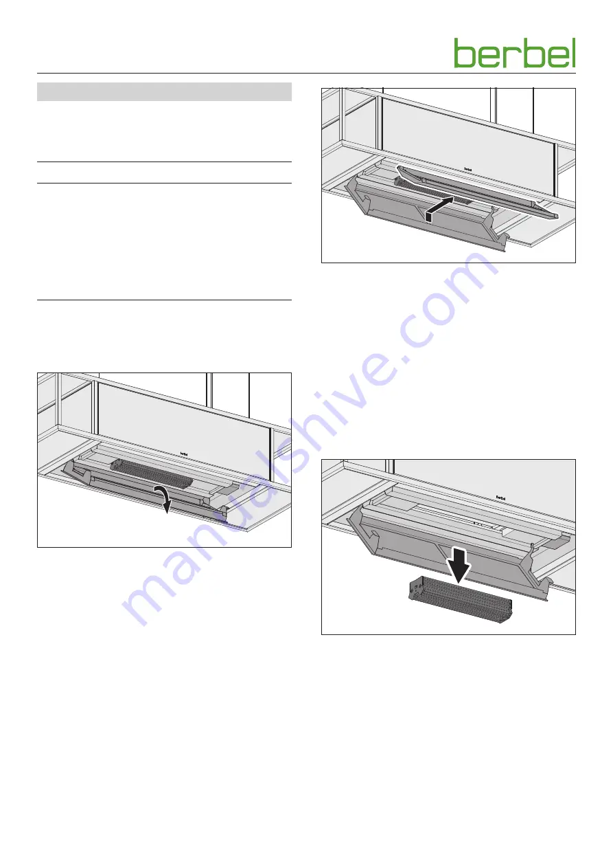
The faceplate with the lower section is held in the device by 
magnets.


Fold the faceplate down.


Lift up the rear lower section.


Take out the front lower section.


Clean the upper section with a soft, moist cloth.


Clean the lower section with a soft, moist cloth or in a 
dishwasher.


Dry the upper and lower sections with a soft cloth.


Insert the front lower section.


Press down the rear lower section.


Fold the faceplate up until the retaining magnets lock in 
audibly.

Capillar Trap

The Capillar Trap is inserted into the device above the lower 
section and is held by a side rail.


Grasp the Capillar Trap on its sides with both hands.


Pull the Capillar Trap out.


Clean the Capillar Trap e.g. in a dishwasher.


Clean the surfaces and edges on the recess for the 
Capillar Trap with a soft, moist cloth.


Make sure that the Capillar Trap is completely dry.


Re-attach the Capillar Trap.

Summary of Contents for Skyline Frame BIH 100 SKF

Page 1: ...EN Island hood Skyline Frame EN Operating and installation instructions for the models BIH 100 SKF BIH 120 SKF BIH 140 SKF BIH 160 SKF 6006244_0 ...

Page 2: ...of a hazardous situation that results in serious injuries or death D WARNING Notes with the word WARNING warn of a hazardous situation that could result in serious injuries or death D CAUTION Notes with the word CAUTION warn of a situation that could result in minor injuries D ATTENTION Notes with the word ATTENTION warn of a situation that could result in damage to property or to the environment ...

Page 3: ... plate 11 3 4 4 Hang the device in place 13 3 4 5 Set the end positions 16 3 4 6 Assemble shelves 17 3 4 7 Set colour temperature 17 3 4 8 Check and carry out commissioning 17 4 Operation 18 4 1 Safety information for operation 18 4 2 Operating the device 18 5 Cleaning 19 5 1 Safety information for cleaning 19 5 2 Cleaning procedures 19 6 Maintenance 21 6 1 Safety information for maintenance 21 6 ...

Page 4: ...erstand the hazards involved with the device y Children may not play with the device 1 3 General safety instructions D WARNING Hazard through a disregard of the operating and installation instructions This manual contains important information for the safe handling of the device Separate reference is made to possible hazards Read through this manual thoroughly Follow the safety instructions in thi...

Page 5: ...ity in the room can be reduced with the fresh air feed In recirculated air mode it is necessary to use the run on function so that the device can remove the remaining odours Using the run on function increases the life of the filter filling The filter filling must be replaced at regular intervals When using the recirculated air filter permalyt BUR BIH optional After the extractor hood is turned of...

Page 6: ...e behind the Capillar Trap D Teach button cover E Hob lighting F Teach button to adjust the stop positions G Additional button to switch the hob lighting on off H Additional button to switch power level 3 on off A B C H G F D I E A Ceiling mounting plate B Screwed end C Mounting sleeve D Support cable E Cover for ceiling mounting plate F Wieland socket G Cable anchor for mains cable H Mains cable ...

Page 7: ...IH regenerative recirculated air filter is supplied optional The fastening materials are only suitable for solid walls 2 6 Technical data Information on the model e g serial number year of construction is quoted on the ratings plate D 2 4 Product overview page 6 Variants without side shelves BIH 100 SKF E01 BIH 120 SKF E01 Connection voltage 230V 50 Hz 230V 50 Hz Total power1 max 300W max 300W Fan...

Page 8: ...Effect lighting LED 26W 2654 lm LED 30W 3082 lm Lighting Ceiling effect lighting 2700 6500 K 2700 6500 K Colour temperature adjustable 2200 6500 K 2200 6500 K Noise power level 3 60 dB A 63 dB A Width 1395 mm 1600 mm Depth 510 mm 510 mm Height 305 mm 305 mm Height adjustability 1200 mm 1200 mm Load capacity max per side max 8 kg 4 kg 8 kg 4 kg Net weight 78 kg 87 kg 1 The total power increases by ...

Page 9: ...Disregard of the ambient conditions can lead to hazardous situations e g in the handling of electrical power or gas Make sure that the requirements for the installation location are complied with y Do not install in potentially explosive atmospheres y With simultaneous use of a heating point which uses air from the room as its oxygen supply e g chimneys y A safety device is absolutely essential y ...

Page 10: ... the way or that could be damaged Make sure that the hob and other parts that could be touched have cooled down Protect the hob and other surfaces in the installation area e g with thick cardboard Ensure that the power supply is switched off and remains so Connect the power supply only when instructed to do so in the installation instructions 3 4 2 Unpack the device D ATTENTION Hazard of glass bre...

Page 11: ...ter of circle over slots 770 mm 1040 mm Determine the hanging position Observe the hob position y The ceiling mounting plate s centre point is directly above the hob s centre point y The ceiling mounting plate runs parallel to the hob Make sure that the legal safety clearances will be complied with y Recommendation 400 mm y With electric hobs at least 650 mm y With gas hobs at least 650 mm Observe...

Page 12: ...nner Ensure that all nuts are fully tightened The ceiling mounting plate is hanging securely and aligned correctly on the ceiling The Wieland socket cable anchor and earthing cable can be installed in the pre drilled positions on either side of the ceiling mounting plate D WARNING Risk of death due to electric shock Touching live parts can cause an electric shock burns or death Ensure that the pow...

Page 13: ...ob Keep the installation area clear 800 Have two persons lift the hood body Align the hood body y The distance to the ceiling mounting plate must be less than 800 mm y The mains cable is at the rear on the right when viewed from the front D ATTENTION Danger of property damage due to improper hanging on the cables The cable cannot be wound up correctly due to obstructions or irregularities on the c...

Page 14: ...the screwed end visible Align the hood body horizontally by adjusting the fastening sleeves Tighten all fastening sleeves using the lock nuts counter nuts on the ceiling mounting plate Ensure that all fastening sleeves are fully tightened on the ceiling mounting plate The hood body is aligned and secured Plug the Wieland plug into the Wieland socket Place the cable anchor into the bracket on the c...

Page 15: ...n When using the recirculated air filter permalyt BUR BIH optional When the device is connected to the power supply for the first time this is confirmed by an acoustic signal y 30x beep for 1 second respectively The device is not correctly connected Check the connection from the device to the extractor hood y Constant tone 3 seconds The device is correctly connected y Initial constant tone 3 secon...

Page 16: ...ger of irreparable property damage through improper operation If the device drives against an obstacle the support cables may be pushed from the rollers Make sure that the route of travel is clear The device and the BFB 6bT remote control must be connected once D 4 2 Operating the device page 18 Use the remote control to move the device upwards Press and hold down the teach button to slow down the...

Page 17: ...ion manual for the remote control 3 4 8 Check and carry out commissioning D ATTENTION Risk of disruptions due to moisture in the device If the device is moved from a cold environment into a hot one condensation may form inside Wait about 2 3 hours before bringing the device into service Check that an all pole isolating device min 3 mm contact gap is present Ensure that air outlets on the device ar...

Page 18: ...able to escape through the ventilation slots without impediment Otherwise backpressure may form If the cooking vapours are no longer able to escape there is a danger of fire Measures to ensure a sufficient supply of fresh air Open the windows Open the doors Ensure that the window contact switch and the wall box are installed and ready for operation With heating points which use air from the room a...

Page 19: ...he dirt particles are separated off and collected in the upper section the lower section and in the Capillar Trap Before every cleaning Turn off the device Make sure that the hob and other parts that could be touched have cooled down D ATTENTION Danger of damage through improper cleaning Sharp edged objects abrasive or unsuitable cleaning agents can damage the device The following cleaning agents ...

Page 20: ...ts Fold the faceplate down Lift up the rear lower section Take out the front lower section Clean the upper section with a soft moist cloth Clean the lower section with a soft moist cloth or in a dishwasher Dry the upper and lower sections with a soft cloth Insert the front lower section Press down the rear lower section Fold the faceplate up until the retaining magnets lock in audibly Capillar Tra...

Page 21: ...ce is fitted with maintenance free LED lighting In the event of a fault Please consult your dealer or customer services 6 2 2 Replacing the filter filling only for BUF BIH recirculated air filter Odours are trapped in the filter filling in the recirculated air filter The odour free cleaned room air is fed back into the room Recirculated air filters are maintenance free for up to two years Then fil...

Page 22: ... consult a qualified electrician The fan does not work y The device is not switched on Check all power levels y The device is connected to a window contact switch and the window is closed Open the window y The device is connected to a safety device The safety device detects a critical under pressure Open a window Wait until the air pressure returns to normal The lighting does not work y The device...

Page 23: ...he device again After a power interruption the Raise button flashes on the remote control y The power supply dropped out whilst the drive motor was in operation The device is in calibration mode and requires a reference run Press the Raise button on the remote control The device moves fully upwards once again and then into the set top end position The Raise and Lower buttons on the remote control ...

Page 24: ...ct the hood body against damage and scratches e g using a blanket Cover the cooled hob Keep the installation area clear 7 1 Dismounting the hood body Set the device down on a suitable surface e g trestle Unscrew the lock nuts on the ceiling console s cover Deposit the cover on the body Pull out the Wieland plug Remove the screws on the strain relief Deposit the mains cable with the Wieland plug on...

Page 25: ...Dispose of filter filling Dispose of the charcoal in accordance with the local applicable Waste Disposal Act EU waste code 061302 8 3 Dispose of the device D ATTENTION Risk of environmental damage due to improper disposal of the device The device is subject to the European Directive 2012 19 EU and should not be disposed of with household waste Do not put the device into the normal household waste ...

Page 26: ...th Low Energy via the remote control or the app Applied standards re 1 y Art 3 1 a Safety requirements EN 60335 1 2012 AC 2014 A11 2014 A13 2018 EN 60335 2 31 2014 EN 62233 2008 AC 2008 EN 61347 1 2015 EN 61347 2 13 2014 EN 62031 2008 A1 2013 A2 2015 EN 62471 2003 y Art 3 1 b Electromagnetic compatibility EN 55014 1 2006 A1 2009 A2 2011 EN 55014 2 1997 AC 1997 A1 2001 A2 2008 EN 55015 2013 EN 6154...

Page 27: ... 80 9 0 Mon to Thu 08 00 17 30 hrs and Fri 08 00 16 30 hrs Fax 49 0 5971 80 80 9 10 Internet www berbel de email info berbel de Contact the manufacturer s customer support department There are several ways for you to contact our customer service Please select from the following options Tel 49 0 5971 80 80 9 0 Mon to Thu 08 00 17 00 hrs and Fri 08 00 15 00 hrs Fax 49 0 5971 80 80 9 10 email service...

Page 28: ...6006244_0 30 05 2022 ...

Reviews: