background image

22

Dismounting

6005437_a – 30.05.2022

7. 

Dismounting


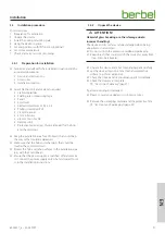
Move the device into a position where the distance to the 
ceiling console is no more than 1150 mm.


D

WARNING!

Risk of death due to electric shock!

Touching live parts can cause an electric shock, burns or 
death.


Disconnect all poles of the power supply for the device.


Ensure that the voltage supply is and remains 
disconnected while the following work is in progress. 


D

WARNING!

Danger of injuries through improper handling!

Taking the device down requires a great deal of physical 
exertion due to its size and weight. If the device falls down, 
serious injuries are possible.


At least three persons are required to take the device 
down.


Ensure stable footing when taking the device down.


Ensure that no other people are in the working area.


D

ATTENTION!

Danger of property damage through improper handling!

Taking the device down requires a great deal of physical 
exertion due to its size and weight. If the device falls, the 
device, kitchen furnishings and other objects could be 
damaged.


Protect the hood body against damage and scratches 
(e.g. using a blanket). 


Cover the cooled hob.


Keep the installation area clear.

7.1 

Dismounting the hood body


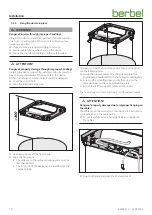
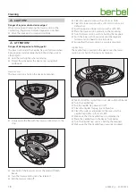
Set the device down on a suitable surface (e.g. trestle).


Unscrew the lock nuts on the ceiling console’s cover. 


Deposit the cover on the body. 


Pull out the Wieland plug. 


Remove the screws from the cable anchor. 


Deposit the mains cable with the Wieland plug on the 
body. 

If present:


Remove any accessory connection cables.


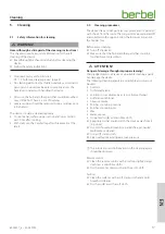
Have two persons hold the body.


Have a third person unscrew the lock nuts (counter nuts) 
for the support cable on the fastening sleeves. 


Unscrew the fastening sleeves from the screwed end and 
loosen the support cable.


Deposit the support cable on the body. 


Secure all moving parts on the hood body. 


Set the body down on a clean, solid surface or in the 
packaging. 

7.2 

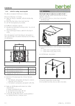
Dismounting the ceiling mounting plate


Remove the nuts and the washers from the slots in the 
ceiling mounting plate. 


Unscrew the nuts from the lock holes in the ceiling 
mounting plate. 


Rotate the ceiling mounting plate. 


Remove the ceiling mounting plate. 


Set the ceiling mounting plate down on a clean, solid 
surface or in the packaging. 


Remove the nuts and the washers from the lock holes. 

The device is dismounted. 

Summary of Contents for Skyline Round BIH 60 SKR

Page 1: ...EN Island hood Skyline Round EN Operating and installation instructions for the models BIH 60 SKR 6005437_a ...

Page 2: ... result in serious injuries or death D CAUTION Notes with the word CAUTION warn of a situation that could result in minor injuries D ATTENTION Notes with the word ATTENTION warn of a situation that could result in damage to property or to the environment Symbol clarification text Handling requirement y Listing D Reference to another point in this document Reference to other documents that should b...

Page 3: ...te 10 3 4 4 Hang the device in place 12 3 4 5 Set end positions with lift function optional 14 3 4 6 Set colour temperature 15 3 4 7 Check and carry out commissioning 15 4 Operation 16 4 1 Safety information for operation 16 4 2 Operating the device 16 5 Cleaning 17 5 1 Safety information for cleaning 17 5 2 Cleaning procedures 17 6 Maintenance 19 6 1 Safety instructions for maintenance 19 6 2 Mai...

Page 4: ...rstand the hazards involved with the device y Children may not play with the device 1 3 General safety instructions D WARNING Hazard through a disregard of the operating and installation instructions This manual contains important information for the safe handling of the device Separate reference is made to possible hazards Read through this manual thoroughly Follow the safety instructions in this...

Page 5: ...e g if steam touches the cold surface is prevented by the ventilation of the hood underside y Part of the vented air quantity is blown in at the sides over the hood underside and directed into the suction gap 2 2 Recirculated air mode The device is used in recirculated air mode The filter filling in the recirculated air filter neutralises any unpleasant odours present The odour free cleaned room a...

Page 6: ...section folds down D Hob lighting E Ratings plate behind the Capillar Trap A D C B E H G F I A Ceiling mounting plate B Mains cable with Wieland plug C Wieland socket D Cable tie E Cover for ceiling mounting plate F Screwed end G Mounting sleeves H Support cable I Lock nut for ceiling mounting plate B C A D F E A Cover for hood body B Cover removable for recirculated air filter C Recirculated air ...

Page 7: ...land socket with 2 metal screws F2 9 x 13 M Operating instructions BFB 6bT N Operating and installation instructions The fastening materials are only suitable for solid walls 2 5 Technical data BIH 60 SKR E02 Connection voltage 230V 50 Hz Total power 272 1W Fan power consumption 170W Drive power consumption 80W Lighting Hob lighting LED 19 5W 2724 lm Lighting Effect lighting LED 2 6W 264 lm Colour...

Page 8: ...isregard of the ambient conditions can lead to hazardous situations e g in the handling of electrical power or gas Make sure that the requirements for the installation location are complied with y Do not install in potentially explosive atmospheres y With simultaneous use of a heating point which uses air from the room as its oxygen supply e g chimneys y A safety device is absolutely essential y T...

Page 9: ...way or that could be damaged Make sure that the hob and other parts that could be touched have cooled down Protect the hob and other surfaces in the installation area e g with thick cardboard Ensure that the power supply is switched off and remains so Connect the power supply only when instructed to do so in the installation instructions 3 4 2 Unpack the device D ATTENTION Hazard of glass breaking...

Page 10: ...mm Determine the hanging position Observe the hob position y The ceiling mounting plate s centre point is directly above the hob s centre point y The ceiling mounting plate runs parallel to the hob Make sure that the legal safety clearances will be complied with y Recommendation 650 mm y With electric hobs at least 650 mm y With gas hobs at least 650 mm Observe the specifications for the cooking a...

Page 11: ... nuts cross wise using the spanner Ensure that all nuts are fully tightened The ceiling mounting plate is hanging securely and aligned correctly on the ceiling The Wieland socket and the earthing cable are installed in the pre drilled positions D WARNING Risk of death due to electric shock Touching live parts can cause an electric shock burns or death Ensure that the power supply is switched off a...

Page 12: ...n area clear 800 Have two persons lift the hood body Align the hood body y The distance to the ceiling mounting plate must be less than 800 mm y The front side of the device can be identified by the company logo Two persons hold the hood body and a third person carries out the following tasks Guide the support cable s mounting sleeves into the appropriate threaded bolts on the ceiling mounting pla...

Page 13: ...ght can cause severe injuries Never unscrew the fastening sleeves completely Ensure that there is no more than 10 mm of thread on the screwed end visible Align the hood body horizontally by adjusting the fastening sleeves Tighten all fastening sleeves using the lock nuts counter nuts on the ceiling mounting plate Ensure that all fastening sleeves are fully tightened on the ceiling mounting plate T...

Page 14: ...age due to falling parts The cover can fall down when it is being removed and damage the hob the kitchen furnishings or other objects When removing the cover hold it tightly in both hands Protect the area below the device e g using thick cardboard D ATTENTION Danger of irreparable property damage through improper operation If the device drives against an obstacle the support cables may be pushed f...

Page 15: ...dividually or synchronously The remote control is used to set the colour temperature Observe the instruction manual for the remote control 3 4 7 Check and carry out commissioning D ATTENTION Risk of disruptions due to moisture in the device If the device is moved from a cold environment into a hot one condensation may form inside Wait about 2 3 hours before bringing the device into service Check t...

Page 16: ...diment Otherwise backpressure may form If the cooking vapours are no longer able to escape there is a danger of fire Measures to ensure a sufficient supply of fresh air Open the windows Open the doors Ensure that the window contact switch and the wall box are installed and ready for operation With heating points which use air from the room as their oxygen supply e g chimneys Make sure that the man...

Page 17: ...he dirt particles are separated off and collected in the upper section the lower section and in the Capillar Trap Before every cleaning Turn off the device Make sure that the hob and other parts that could be touched have cooled down D ATTENTION Danger of damage through improper cleaning Sharp edged objects abrasive or unsuitable cleaning agents can damage the device The following cleaning agents ...

Page 18: ...er section with a soft moist cloth Clean the lower section with a soft moist cloth or in a dishwasher Dry the upper and lower sections with a soft cloth Place the lower section centrally on the mounting Turn the lower section until it is held by the magnets Push the lower section upwards until the magnetic fasteners can be heard to click into place Ensure that the lower section is securely mounted...

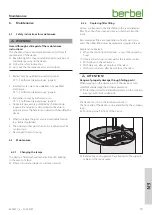
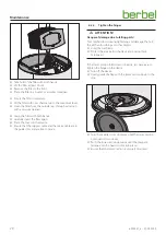
Page 19: ...ng 6 2 Maintenance 6 2 1 Changing the lamps The device is fitted with maintenance free LED lighting In the event of a fault Please consult your dealer or customer services 6 2 2 Replacing filter filling Odours are trapped in the filter filling in the recirculated air filter The odour free cleaned room air is fed back into the room Recirculated air filters are maintenance free for up to two years T...

Page 20: ...able are in the guide slots and are free to move 6 2 3 Tighten the hinges D ATTENTION Danger of damage due to falling parts Tool may fall down during tightening and damage the hob the kitchen furnishings or other objects Hold the tool firmly Protect the area below the device e g using thick cardboard If the lower section folds down too easily it is necessary to tighten the hinge on the device Turn...

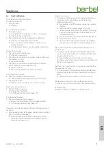
Page 21: ... units and the ceiling y Smoke development by heating cooking oils and cooking fats to too high a temperature Note the smoke point of the cooking oil or fat you are using You can obtain this information from the respective manufacturer Moisture in the device y Dripping or splashing water has penetrated the device y Liquid e g from vases bottles on the device has penetrated the device Immediately s...

Page 22: ...t the hood body against damage and scratches e g using a blanket Cover the cooled hob Keep the installation area clear 7 1 Dismounting the hood body Set the device down on a suitable surface e g trestle Unscrew the lock nuts on the ceiling console s cover Deposit the cover on the body Pull out the Wieland plug Remove the screws from the cable anchor Deposit the mains cable with the Wieland plug on...

Page 23: ...spose of filter filling Dispose of the charcoal in accordance with the local applicable Waste Disposal Act EU waste code 061302 8 3 Dispose of the device D ATTENTION Risk of environmental damage due to improper disposal of the device The device is subject to the European Directive 2012 19 EU and should not be disposed of with household waste Do not put the device into the normal household waste at...

Page 24: ...remote control or the app Applied standards re 1 y Art 3 1 a Safety requirements EN 60335 1 2012 AC 2014 A11 2014 A13 2018 EN 60335 2 31 2014 EN 62233 2008 AC 2008 EN 61347 1 2015 EN 61347 2 13 2014 EN 62031 2008 A1 2013 A2 2015 EN 62471 2003 y Art 3 1 b Electromagnetic compatibility EN 55014 1 2006 A1 2009 A2 2011 EN 55014 2 1997 AC 1997 A1 2001 A2 2008 EN 55015 2013 EN 61547 2009 EN 61000 3 2 20...

Page 25: ... 80 9 0 Mon to Thu 08 00 17 30 hrs and Fri 08 00 16 30 hrs Fax 49 0 5971 80 80 9 10 Internet www berbel de email info berbel de Contact the manufacturer s customer support department There are several ways for you to contact our customer service Please select from the following options Tel 49 0 5971 80 80 9 0 Mon to Thu 08 00 17 00 hrs and Fri 08 00 15 00 hrs Fax 49 0 5971 80 80 9 10 email service...

Page 26: ...26 6005437_a 30 05 2022 ...

Page 27: ...27 6005437_a 30 05 2022 ...

Page 28: ...6005437_a 30 05 2022 ...

Reviews: