background image

1

TABLE OF CONTENTS 

INTRODUCTION   .................................................................................................................................................... 2 

SAFETY PRECAUTIONS   ...................................................................................................................................... 3 

SAFETY DECALS   .................................................................................................................................................. 5 

ASSEMBLY 
  Conversion 

Table, 

Glossary, 

Tools 

Required 


........................................................................... 


Step 1:  Vehicle Preparation ...................................................................................................................... 7 


Step 2:  Subframe Preparation  ................................................................................................................. 7 

  Installing 

the 

Winch 

Hook 


........................................................................................................... 11 


Verify Skid Shoe Adjustment  ...................................................................................................... 11 


Step 3:  Engine Preparation   ..................................................................................................................... 12 

  Saddle 

Preparation 


..................................................................................................................... 12 

OPERATION 
 

Operating the Snowblower  ....................................................................................................................... 13 


Electric Controls   ........................................................................................................................................ 13 

 Removing 

Snow 


........................................................................................................................................ 13 


Clearing a Clogged Chute  ........................................................................................................................ 13 

MAINTENANCE 
 Maintenance 


.............................................................................................................................................. 14 

 Adjustments 


.............................................................................................................................................. 14 

 Lubrication 


................................................................................................................................................. 14 


Cutting Edge Maintenance  ....................................................................................................................... 14 


Snowblower Pulley Replacement   ............................................................................................................ 14 


Auger and Fan Shear Bolt Replacement  ................................................................................................. 14 

BELT REPLACEMENT   .......................................................................................................................................... 14 

BELT ADJUSTMENTS  ........................................................................................................................................... 14 

REPLACEMENT OF ONE OR TWO SECTIONS OF THE AUGER AND /OR GEAR BOX   ............................. 

14 

DISMOUNTING & STORAGE    .............................................................................................................................. 19 

TROUBLESHOOTING   ........................................................................................................................................... 20 

TORQUE SPECIFICATION TABLE   ...................................................................................................................... 21 

PARTS BREAKDOWN AND PARTS LIST 
 

Rotation System with Chute   ..................................................................................................................... 22 


Saddle Assembly   ...................................................................................................................................... 24 

 Subframe 


................................................................................................................................................... 26 

 Snowblower 


............................................................................................................................................... 28 

OPTIONS   

....................................................................................................................................................... 32 

PAGE

Summary of Contents for 700360-6

Page 1: ...SAFETY RULES INSTRUCTIONS BEFORE OPERATING YOUR EQUIPMENT J 07 ASSEMBLY REPAIR PARTS OPERATION MAINTENANCE 105192_EN OWNER S MANUAL Model Number 700360 6 Snowblower 105192_EN BERCO PRESTIGE 54 SNOWBLOWER for ALL TERRAIN VEHICLES ...

Page 2: ...ized dealer within the warranty period for repairs In the event that defective merchandise must be returned to manufacturer for repairs the dealer must first obtain a written authorization from either KIMPEX or BERCOMAC freight fees are prepaid prior to the shipment This warranty extends only to equipment operated under normal conditions To validate a warranty claim it is the user s responsibility...

Page 3: ...r 13 Electric Controls 13 Removing Snow 13 Clearing a Clogged Chute 13 MAINTENANCE Maintenance 14 Adjustments 14 Lubrication 14 Cutting Edge Maintenance 14 Snowblower Pulley Replacement 14 Auger and Fan Shear Bolt Replacement 14 BELT REPLACEMENT 14 BELT ADJUSTMENTS 14 REPLACEMENT OF ONE OR TWO SECTIONS OF THE AUGER AND OR GEAR BOX 14 DISMOUNTING STORAGE 19 TROUBLESHOOTING 20 TORQUE SPECIFICATION T...

Page 4: ...REGARDLESS OF THE HAZARD BE EXTREMELY CAREFUL DANGER Signals an extreme hazard that will cause serious injury or death if recommended precautions are not followed WARNING Signals a hazard that may cause serious injury or death if the recommended precautions are not followed CAUTION Signals a hazard that may cause minor or moderate injury if the recommended precautions are not followed Record your ...

Page 5: ...nd remove door mats all foreign objects and the like 2 For motorized accessories disengage all clutches and shift into neutral before starting engine 3 Do not operate the accessory without wearing adequate winter outer garments Avoid loose fitting clothing that can get caught in moving parts Wear footwear that will improve footing on slippery surfaces 4 Handle fuel with care it is highly flammable...

Page 6: ...ders it might throw gravel or debris that can hurt people or damage property 9 Never operate the accessory at high transport speeds on slippery surfaces Use care when backing up 10 Do not carry passengers 11 Disengage power to the accessory when it is transported or not in use 12 Never operate the accessory without good visibility or light 13 Keep the accessory away from heat sources or flames MAI...

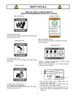
Page 7: ... reading owner s manual DECAL 105126 DECAL 105128 DECAL 105127 DECAL 105130 Before installing or using Locate read and make sure to understand all of the owner s manual DECAL 105131 Refer to owner s manual about wearing safety glasses ear muffs and mask Refer to owner s manual for use of counter weights cat tracks and tire chains 1 Do not drive faster than 3 KM H when the snowblower is in operatio...

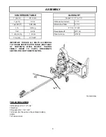
Page 8: ...OLS REQUIRED 3 Wrenches 9 16 1 2 3 4 1 Ratchet 3 Sockets 9 16 1 2 3 4 1 Wrench for the nuts on the vehicle s battery posts 1 Wooden block CONVERSION TABLE 1 po in 25 4 mm 1 pi ft 0 3 m 1 psi lb in2 6 89 kPa 1 lb 0 45 kg 1 lbf 4 4 N 1 m h mi h 1 61 km 1 hp cv 0 75 kW GLOSSARY Quad V T T A T V Véhicule tout terrain V T T All terrain vehicle A T V Power take off P T O Prise de force P D F P T O P D F...

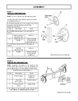
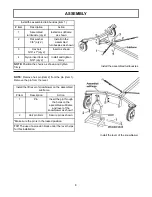
Page 9: ...ame See below STEP 1 VEHICLE PREPARATION NOTE A 1 7 8 or 50 mm tow hitch ball is required A Install the lift strap item 1 by looping it around the suspension arm as shown on the vehicle Tighten the loop firmly Item Description Action B Install the brackets item 3 on both sides of vehicle Bolt and nut from suspension arm Remove 2 3 Flat washer and bracket Install and lightly secure with the origina...

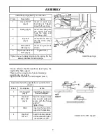
Page 10: ...insert lock nut 5 16 qty 2 Install and tighten firmly NOTE Position the chains as shown and tighten firmly Install the lift lever of snowblower on the assembled subframe Item Description Action 1 Pin Insert the pin through the holes on the assembled subframe and lever of the snowblower as shown 2 Hair pin 4mm Secure pin as shown Make sure the pin is in the locked position TIP The use of a wooden b...

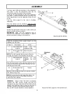
Page 11: ...cedure for both springs Install the springs ASSEMBLY Assemble the hitch support Assemble the hitch supports item 1 and the hitch item 3 Item Description Action 1 Hitch support qty 2 Install the supports on the hitch support 2 Hex bolt 3 8 x 3 4 qty 4 Insert in chosen holes two on each side and secure with the flange nuts 3 8 Tighten firmly 3 Hitch Insert on the two hitch supports if applicable 4 H...

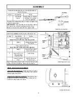
Page 12: ...led hitch support item1 on the vehicle s tow hitch ball Item Description Action 1 Assembled hitch support Insert onto the adjustment tube 2 3 Pin and 3mm hair pin Secure in place NOTE The hitch support has two sets of holes to increase the length of the subframe if necessary 1 Assembled hitch support Attach on the vehicle s tow hitch ball Tip Turn the wheels on the support towards the front to pre...

Page 13: ... the turnbuckles firmly in order to tighten the vehicle s suspension IMPORTANT After adjusting the turnbuckles tighten the nuts on the vehicle s suspension arms firmly Make sure to lock the nuts with the original locks Attach the vehicle s winch s hook on the lever rod Item Description Action If the vehicle s winch is higher than 20 510mm from the ground 1 Sleeve Install in the top hole of the lev...

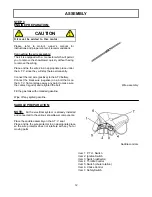
Page 14: ...away any paint to make sure the contact is good and retighten the bolt Fill the gas tank with unleaded gasoline Wipe off any spilled gasoline Saddle controls STEP 3 ENGINE PREPARATION Item 1 P T O Switch Item 2 Ignition Switch Item 3 Switch deflector Item 4 Throttle Control Item 5 Switch chute rotation Item 6 Choke Control Item 7 Safety Switch SADDLE PREPARATION NOTE All the electrical system is a...

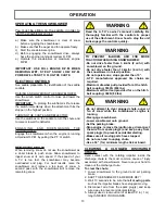
Page 15: ...ttempt to clear plugged chute auger or fan of snow while the snowblower s engine is running Disengage snowblower Lower snowblower onto ground Set the parking brake Stop engine remove the ignition key disconnect the wire from spark plug s and keep away from spark plug s to prevent accidental starting Make sure all moving parts have stopped Do not use hand to unplug chute Use a 36 1m minimum length ...

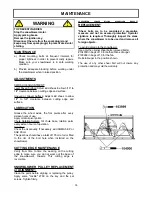
Page 16: ...MAINTENANCE CUTTING EDGE MAINTENANCE Verify from time to time the wearing on the cutting edge to make sure you do not wear out the base of the snowblower s chassis This cutting edge is reversible AUGER AND FAN SHEAR BOLT REPLACEMENT Shear bolts are to be considered a preventive measure and not an assured protection Operator vigilance is required Thoroughly inspect the areas where the snowblower is...

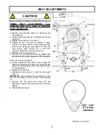
Page 17: ...ine on top c Loosen slightly the four nuts item 7 and the two nuts item 8 needed to apply tension to the belt d Remove the six nuts item 3 and bolts from the reduction plate item 4 e Remove the reduction plate f Unhook the spring item 5 from the slot on the tension arm item 6 and remove the tension arm g Remove the V belt h Replace the timing belt IMPORTANT Make sure the notches of the belt are we...

Page 18: ... the four nuts item 7 f Turn the fan by hand a few turns and make sure the timing belt is well engaged on the sprocket If the belt is not well engaged g Loosen slightly the nuts item 7 and re align the pulleys by adjusting the angle of the reduction box item 10 using the play of the bolt holes as shown on following page h Retighten the four nuts I Reinstall the spring item 5 and the belt guard ite...

Page 19: ...ustment The pulleys are well aligned and the timing belt stays completely engaged on the sprocket Improper adjustment The pulleys are not well aligned and the timing belt does not stay completely engaged on the sprocket you have to realign the pulleys by adjusting the angle of the reduction box CAUTION Never use the snowblower without the belt guard ...

Page 20: ...remove tension on the belts i Remove the reduction box item 11 j Loosen the set screws item 2 on the bearing and the pulley behind the snowblower k Remove the timing belt sprocket item 5 from the gear box shaft l Remove all the bolts item 6 and the nuts that support the gear box and its support m Remove the assembly gear box its support the fan and augers from the snowblower and save the nylon bus...

Page 21: ...e of the turnbuckles in order to keep the adjustment the hook from the winch and the hitch from the rear of the vehicle f Carefully back up the A T V from over the subframe STORAGE a Clean snowblower and subframe thoroughly and repaint all parts from which paint has worn b List the replacement parts that will be needed before the next season c Follow the instructions in the lubrication section d S...

Page 22: ...ed when already plugged Make sure auger fan are not plugged or frozen before engaging snowblower Chute rotation is difficult Dirt or ice may be underneath chute Clean the base of chute the rotation ring Lubricate chute inside out and the rotation worm The base of the chute may be damaged or bent Replace defective parts The chute plugs easily Snowblower engine is turning too slowly Always have engi...

Page 23: ...4 298 3 358 3 4 19 05 150 185 203 3 250 7 270 324 366 1 439 3 380 456 515 3 618 3 7 8 22 23 160 200 216 8 271 400 480 542 4 650 9 600 720 813 6 976 3 1 25 4 250 300 338 8 406 5 580 696 786 5 943 8 900 1080 1220 4 1464 5 METRIC BOLT TORQUE SPECIFICATIONS COARSE THREAD Size Screw Grade No Pitch mm Foot Pounds Newton Meters Pitch mm Foot Pounds Newton Meters M6 4T 1 00 3 6 5 8 4 9 7 9 7T 5 8 9 4 7 9 ...

Page 24: ...22 PARTS BREAKDOWN ROTATION SYSTEM WITH CHUTE ...

Page 25: ...ard Fourche protectrice 1 102012 17 Hex bolt 1 4 n c x 3 4 Boulon hex 1 4 n c x 3 4 4 O L 18 Hex bolt 1 4 n c x 1 Boulon hex 1 4 n c x 1 4 O L 19 Hex bolt 1 4 n c x 1 1 2 Boulon hex 1 4 n c x 1 1 2 3 O L 20 Hex bolt 1 4 n c x 1 3 4 Boulon hex 1 4 n c x 1 3 4 3 O L PARTS LIST ROTATION SYSTEM WITH CHUTE 21 Nylon insert lock nut 5 16 n c Écrou à garniture de nylon 5 16 n c 2 O L 22 Nylon insert lock ...

Page 26: ...24 PARTS BREAKDOWN SADDLE ASSEMBLY ...

Page 27: ...eur 2 103381 8 Rubber boot Capuchon de caoutchouc 2 103379 9 Throttle control Contrôle de l accélérateur 1 104008 10 Choke control Contrôle de l étrangleur 1 104009 11 Wire assembly Fil assemblé 1 104017 12 Wire assembly Fil assemblé 1 104018 13 Wire assembly Incl 103382 Fils assemblés Incl 103382 1 104295 14 Pop rivet 3 16 no AD 66BS Rivet pop 3 16 no AD 66BS 4 O L 15 Carriage bolt 5 16 n c x 1 B...

Page 28: ...26 PARTS BREAKDOWN SUBFRAME ...

Page 29: ...104638 15 Hitch support Support d attache 2 104641 16 Hitch Attache 1 104639 17 Hitch ball support Support de boule d attelage 1 104640 18 Pin Goupille 1 104642 19 Eye bolt Boulon à oeillet 2 102087 20 Spring Ressort 2 103073 PARTS LIST SUBFRAME 21 Bracket Fixation 2 105194 22 Hex bolt 5 16 n c x 1 Boulon hex 5 16 n c x 1 2 O L 23 Hex bolt 3 8 n c x 3 4 Boulon hex 3 8 n c x 3 4 12 O L 24 Hex bolt ...

Page 30: ...28 PARTS BREAKDOWN SNOWBLOWER ...

Page 31: ... de tension 1 103985 14 V pulley Poulie en V 1 103739 15 Flat pulley Poulie plate 1 102839 16 Electric clutch Embrayage électrique 1 103998 17 Engine CH 23 Kohler Moteur CH 23 Kohler 1 104003 18 Clutch spacer Espaceur d embrayage 1 103975 19 Flange washer Rondelle à bride 1 103976 20 Clutch support Support d embrayage 1 103980 PARTS LIST SNOWBLOWER 21 Belt guard Garde courroie 1 103979 22 Key 1 4 ...

Page 32: ... 43 Tension bar Barre de tension 1 103995 44 Spring washer Rondelle à ressort 6 104007 45 Gear box left rotation Boîte d engrenage rotation gauche 1 104718 46 Right hitch Attache droite 1 104897 47 Left hitch Attache gauche 1 104898 48 Lever Levier 1 104899 49 Link Lien 1 104900 50 Left spring link Lien du ressort gauche 1 103977 51 Right spring link Lien du ressort droit 1 103978 52 Pin Goupille ...

Page 33: ...c x 1 1 4 4 O L 74 Hex bolt 7 16 n c x 1 1 2 Boulon hex 7 16 n c x 1 1 2 2 O L 75 Hex bolt 7 16 n f x 1 1 2 Boulon hex 7 16 n f x 1 1 2 1 O L 76 Hex bolt 7 16 n c x 5 1 2 Boulon hex 7 16 n c x 5 1 2 1 O L 77 Hex bolt 1 2 n c x 2 1 4 Boulon hex 1 2 n c x 2 1 4 1 O L 78 Machine screw P H 10 x 32 x 1 1 2 Vis mécanique P H 10 x 32 x 1 1 2 2 O L 79 Machine screw T H 1 4 n c x 1 2 Vis mécanique T H 1 4 ...

Page 34: ...TENSION AND SIDE WIDENING ANGLE KIT 700461 Widens the snowblower by 6 and adds about 7 to the height EXTENSION PANEL 700473 Adds about 10 to the height of the snowblower SUBFRAME EXTENSION 700475 For bigger vehicle ...

Page 35: ...___________ _____________________________________________________________________________________________ _____________________________________________________________________________________________ _____________________________________________________________________________________________ _____________________________________________________________________________________________ ____________...

Page 36: ...34 WHEN PERFORMANCE DEPENDABILITY ARE NON NEGOTIABLE Bercomac Limitée 92 Fortin North Adstock Quebec Canada G0N 1S0 WWW BERCOMAC COM PRINTED IN CANADA ORIGINAL NOTICE BY ...

Reviews: