background image


ASSEMBLY 


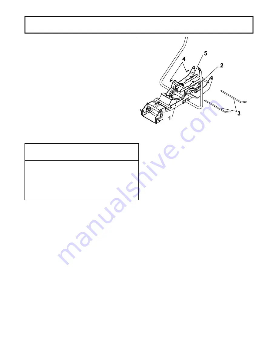
Lift the drive mechanism (item 5) under the subframe. 
Place the V-belt (item 1) around the tractor’s motor 
pulley then around the drive mechanism pulley (item 
2). Secure the drive mechanism in place with the pins 
(item 3) and secure in place 2.5 mm hair pins (item 
4). 
 

NOTE:

 Check to make sure the drive mechanism 

works well.


Check to be sure the belt does not touch the belt 
guides at any time. Do this verification when the 
motor is not running. 
 
If the belt touches the belt-guide, unscrew the bolt on 
the pulley and adjust the guide. Retighten the bolt.


Install drive mechanism 

WARNING


TO PREVENT INJURIES: 
It is the person who installs the drive mechanism’s 
responsibility to make sure that when the clutch is 
disengaged that all moving parts stop. 
 
For more information, do not hesitate to contact 
the technical support. 

Summary of Contents for BERCO 700303-1

Page 1: ...700304 1Subframe 700303 1 Drive Mechanism 104281 BERCO COMPACT MOUNTING KIT for TORO HXL 1638 Tractors F 11 ASSEMBLY REPAIR PARTS OPERATION MAINTENANCE CAUTION READ FOLLOW ALL SAFETY RULES INSTRUCTIO...

Page 2: ...or faulty workmanship COMMERCIAL OR RENTAL USE Warranty on Berco attachments used for commercial or rental purposes is limited to 90 days This warranty does NOT cover Wear items such as shear pins an...

Page 3: ...5 Snowblower Installation 9 Rotary Broom Installation 11 Blade Installation 13 MAINTENANCE DISMOUNTING Maintenance 14 Drive Mechanism Dismounting 14 Subframe Dismounting 14 End of Season Storage 14 T...

Page 4: ...cause serious injury or death if recommended precautions are not followed WARNING Signals a hazard that may cause serious injury or death if the recommended precautions are not followed CAUTION Signa...

Page 5: ...your best insurance against an accident Read this section carefully before operating the tractor and attachment Failure to observe the following safety instructions could result in serious injury All...

Page 6: ...nufacturer such as wheel chains counterweights cabs You must use 100 lbs of rear counterweight for better traction and a greater stability at all times when using an attachment that is installed on th...

Page 7: ...U channel behind the axle the support plate with two holes item 2 Secure with two 5 16 x 1 hex bolts item 3 and flange nuts Install the support plate with one hole item 4 as shown Secure with a 3 8 x...

Page 8: ...2 welded on the pivot support item 3 Secure the other end in the fork item 4 with a pin item 5 the head toward the outside a flat washer item 6 and 2 5 mm hair pin item 7 Install the handle support it...

Page 9: ...Tractors with an electric clutch This kit is assembled for tractors with an electric clutch There are no modifications to be made NOTE It may become necessary to adjust the length A to apply the righ...

Page 10: ...sm works well Check to be sure the belt does not touch the belt guides at any time Do this verification when the motor is not running If the belt touches the belt guide unscrew the bolt on the pulley...

Page 11: ...n instructions 9 WARNING 9 TO PREVENT INJURIES Stop the motor Apply parking brake Remove the ignition key Disconnect the wire from the spark plug s and keep away from spark plug s to prevent accidenta...

Page 12: ...ont tires 14 15 psi Back tires 7 8 psi Tire pressure must be even on both sides of tractor Install handle Adjust skid shoes 9 WARNING 9 TO PREVENT INJURIES It is the person who installs the drive mech...

Page 13: ...have not flipped on their sides in the pulleys and that they do not touch the belt guides Install rotary broom Item 1 Drive mechanism pulley Item 2 Rotary broom pulley 9 WARNING 9 FOR YOUR SECURITY Re...

Page 14: ...m 2 as shown Install the handle on the control rod item 3 as shown and secure with a 2 5 mm hair pin item 4 VERIFY TIRE PRESSURE Check and adjust tractor tire pressure as follows Front tires 14 15 psi...

Page 15: ...ecure with a 2 5 mm hair pin item 4 VERIFY TIRE PRESSURE Check and adjust tractor tire pressure as follows Front tires 14 15 psi Back tires 7 8 psi Tire pressure must be even on both sides of the trac...

Page 16: ...P T O clutch cable shield from the slot by unscrewing the nuts and unhook the cable from the spring d Dismount the drive mechanism by supporting it remove the pins Lower it to the ground carefully Rem...

Page 17: ...324 366 1 439 3 380 456 515 3 618 3 7 8 22 23 160 200 216 8 271 400 480 542 4 650 9 600 720 813 6 976 3 1 25 4 250 300 338 8 406 5 580 696 786 5 943 8 900 1080 1220 4 1464 5 Thick nuts must be used wi...

Page 18: ...16 PARTS BREAKDOWN NOMENCLATURE DES PI CES SUBFRAME SOUS CH SSIS...

Page 19: ...12 Support Support 1 103257 13 Pin Goupille 2 102189 14 Hair pin 2 5mm Goupille ressort 2 5mm 3 102013 15 Support plate Plaque de support 1 103258 16 Support plate Plaque de support 1 103260 17 Hex bo...

Page 20: ...18 PARTS BREAKDOWN NOMENCLATURE DES PI CES DRIVE MECHANISM M CANISME D ENTRA NEMENT...

Page 21: ...n c x 2 Boulon hex 3 8 n c x 2 1 O L 10 Nylon insert lock nut 3 8 n c crou garniture de nylon 3 8 n c 1 O L 11 Spring 1 2 Ressort 1 2 1 102003 12 Spring Ressort 1 102152 13 Spacer Espaceur 2 103003 14...

Page 22: ...l type fits on a wide variety of lawn and garden tractors ROTARY TILLER 700312 Mounts to the rear of lawn garden tractors 14 to 25 HP Comes complete with drive manual lift mechanisms mounting hardware...

Reviews: