INS
TALLER MANU
AL
22
F4
F1
F1
(F3)
F2
(F5)
F4
(F3)
A1
A2
OFF
ON
A1
1
v
+
2
A3
A2
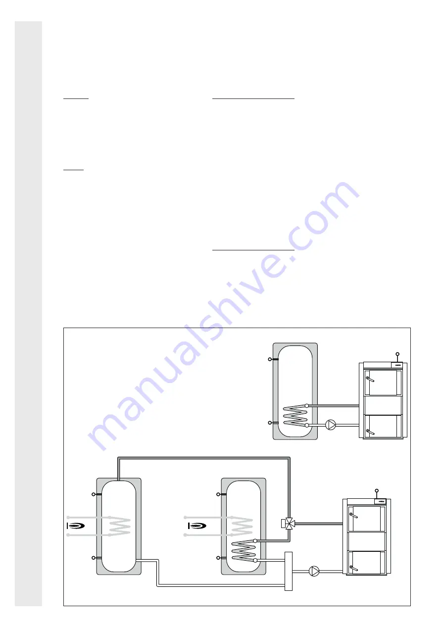
System 2
Outputs:
A1
Solid fuel boiler pump
A2
Valve for switching to storage cylinder
2 (when F2 fitted), or Additional relay,
freely programmable function.
A3 Additional relay, freely programmable
function
Inputs:
F1
Solid fuel boiler probe
F4
temperature probe at bottom of stor-
age cylinder 1/ A1 max. temp. moni-
toring (when F3 not fitted)
F2
temperature probe at bottom of stor-
age cylinder (if present)
F3
(optional) temperature probe at top
of storage cylinder 1 / A1 max. temp.
monitoring, reference probe during
heating
F5
(optional) temperature probe at top of
storage cylinder 2, reference probe
for return temperature control
Impulse (optional) pulse input for circulating
pump controlled by impulses.
Switching conditions for A1
Heat production (difference between storage
cylinder and min. temp.)
ON: F1-F4 > P30 and F1 > P43 + 5°C
or F1-F2 > P32 and F1 > P43 + 5°C
OFF: F1-F4 < P31 and F1-F2 < P33
or F1 < P43
Maximum storage cylinder temperature
OFF: F3 (or F4) > P50 and F5 (or F2) > P51
ON: F3 (or F4) < P50 - 5°C
or F5 (or F2) < P51 - 5°C
Maximum solid fuel boiler temperature:
OFF: F1 > P44
ON: F1 < P44 - 10°C
Switching conditions for A2
ON: A1 = ON and F3 (or F4) > P50
or F1-F4< P31
OFF: A1 = OFF
or F3 (or F4) < P50 - 5°C
or F1-F4 > P30
Fig. 2.10


