background image

20

EXCLUSIVE

4.1  Access to the technical parameters

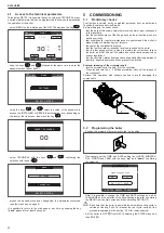
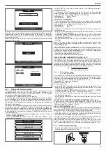
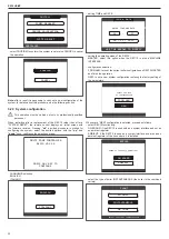
Through the REC10 it is possible to access, using the TECHNICAL menu, 

a series of parameters that can be programmed to allow you to personalise 

the operation of the boiler:

 - select MENU on the initial page of the REC10 and press the key 

18/05/2013

12:17

INFO

SET

30

°C
.3

MENU

FRI

STATE

PLANT

HOT WATER TEMPERATURE

1.3 bar

MENU

STATE

SET

INFO

PLANT

HOT WATER TEMPERATURE

FRI

 - keep the keys 

 and 

 pressed at the same time to enter the 

password menu (about 5 sec)

18/11/2013

12:17

FRI

SETTINGS

MENU

SELECT OPTION

MENU

SETTINGS

SELECT OPTION

FRI

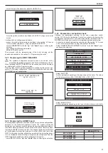
 - using the keys 

 and 

  select the value of the password to 

access the INSTALLER or SERVICE authorisation level, depending on 
the level of the tree menu, then press the key 

00

INSERT PASSWORD

INSERT PASSWORD

 - select TECHNICAL with the keys 

and 

, confirming the 

selection with the key 

SETTINGS

TECHNICAL

SELECT OPTION

MENU

SELECT OPTION

SETTINGS

TECHNICAL

MENU

 - access the desired menu and change/view the parameter concerned 

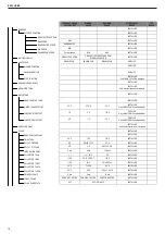
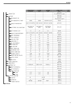
(see the menu tree on page 8).

It is possible to return to the start page at any time by keeping the key 

“back”

 pressed for at least 2 seconds.

5  COMMISSIONING

5.1  Preliminary checks

First ignition is carried out by competent personnel from an authorised 

Technical Assistance Service Beretta.

Before starting up the boiler, check:

 - that the data of the supply networks (electricity, water, gas) correspond 

to the label data

 - that the extraction pipes of the flue gases and the air suction pipes are 

working correctly

 - that conditions for regular maintenance are guaranteed if the boiler is 

placed inside or between items of furniture

 - the seal of the fuel adduction system

 - that the fuel flow rate corresponds to values required by the boiler

 - that the fuel supply system is sized to provide the correct flow rate to 

the boiler, and that it has all the safety and control devices required by 

current regulations

 - that the circulator rotates freely because, especially after long periods of 

inactivity, deposits and/or debris can prevent free rotation.

Eventual releasing of the circulator shaft

 - Insert a screwdriver in the hole (

1

) of the circulator.

 - Press (

a

) and turn the n° 2 Phillips screwdriver (

b

) until the release of 

the crankshaft.

Perform  this  operation  with  extreme  caution  to  avoid  damaging  the 

components.

a

b

1

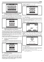
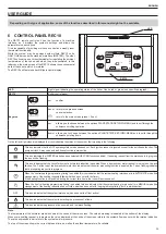
5.2  Programming the boiler

 - Position the system’s master switch to the “on” position.

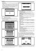
 - If  necessary  set  the  TIME  and  DATE  setting  the  HOURS,  MINUTES, 

DAY, MONTH and YEAR with the keys 

“up”

 and 

“down”

, confirming 

the selection.

 -

12

17

:

ENTER TIME AND DATE

TIME & DATE

USE THE ARROWS TO MODIFY

18 / 11 / 2013

ENTER TIME AND DATE

TIME & DATE

USE THE ARROWS TO MODIFY

Note: it is possible to change the TIME and DATE settings, as well as 

LANGUAGE and the duration of the back-lighting, also later by entering 

the MENU from the main screen and then selecting SETTINGS.


b

Each time that the boiler is powered an automatic venting cycle is 

carried out lasting 2 min. To interrupt the vent cycle, carry out the 

procedure explained in the section 

“5.3 First commissioning”.

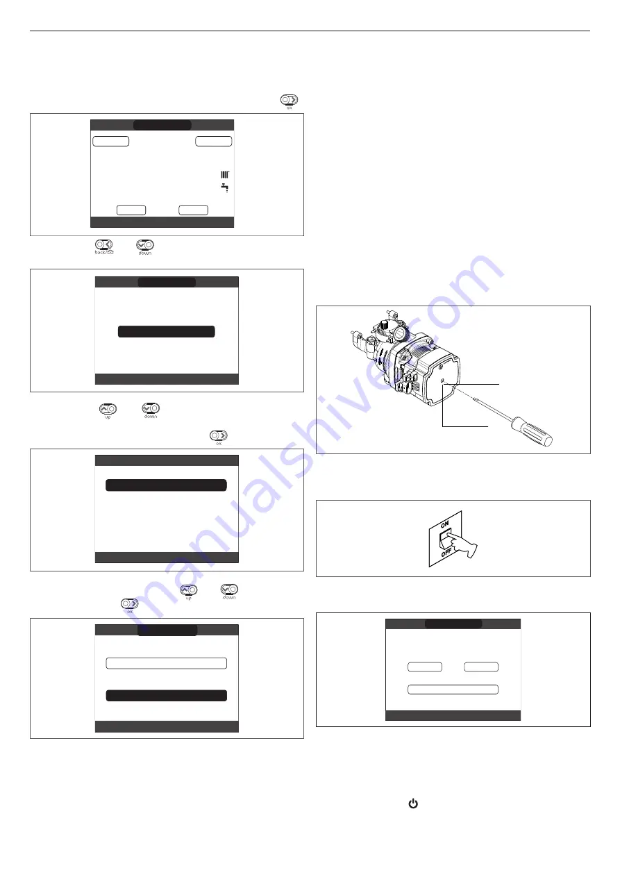
 - Set the boiler to OFF   from REC10 selecting the STATE menu and 

then BOILER.

Summary of Contents for EXCLUSIVE C

Page 1: ...DE INSTALARE ŞI UTILIZARE PL PODRĘCZNIK INSTALATORA I UŻYTKOWNIKA SR PRIRUČNIK ZA INSTALATERE I KORISNIKE EN INSTALLER AND USER MANUAL ES MANUAL PARA EL INSTALADOR Y EL USUARIO PT MANUAL DO INSTALADOR E UTILIZADOR HU FELHASZNÁLÓ ÉS TELEPÍTŐ KÉZIKÖNYV ...

Page 2: ...nd adequate preparation a a PROHIBITED for actions THAT MUST NOT be performed Section destined for user also Warning This instructions manual contains data and information for both the user and the installer Specifically note that the user for the use of the appliance must refer to chapters Warnings and safety Maintenance a a The user must not perform operations on the safety devices replacing par...

Page 3: ...decuada preparación a a PROHIBIDO para acciones que NUNCA DEBEN realizarse Sección destinada únicamente para el usuario Atención Este manual de instrucciones contiene datos e información tanto para el usuario como para el instalador Específicamente tener en cuenta que el usuario para el uso del aparato debe consultar los capítulos Advertencias y seguridades Mantenimiento a a El usuario no debe rea...

Page 4: ...ada a a PROIBIDO para ações que NÃO DEVEM absolutamente ser executadas Seção destinada ao usuário Advertência Este manual de instruções contém dados e informações destinados tanto ao utilizador quanto ao instalador Especificamente ele informa que o utilizador para a utilização da caldeira deve consultar os capítulos a seguir Advertências e seguranças Manutenção a a O utilizador não deve intervir n...

Page 5: ...lumok szerepelnek b b FIGYELEM megfelelő körültekintést és felkészülést igénylő tevékenységek a a TILOS olyan műveletekhez amelyeket TILOS végrehajtani A felhasználónak is szóló rész Figyelem Ez a kézikönyv mind a felhasználó mind a telepítő számára tartalmaz adatokat és információkat Tájékoztatjuk a felhasználót hogy a készülék használatához a következő fejezeteket kell tanulmányoznia Figyelmezte...

Page 6: ...ă o atenţie deosebită şi o pregătire corespunzătoare a a INTERZIS pentru acţiuni care NU TREBUIE să fie efectuate Secţiune destinată de asemenea pentru utilizator Avertisment Prezentul manual de instrucţiuni conţine date şi informaţii destinate atât utilizatorului cât şi instalatorului În mod specific reţineţi că utilizatorul pentru utilizarea aparatului trebuie să se refere la capitole Avertismen...

Page 7: ...ególnej staranności i odpowiedniego przygotowania a a ZABRONIONE dotyczy czynności których NIE WOLNO wykonywać Sekcja przeznaczona również dla użytkownika Ostrzeżenie Podręcznik zawiera dane oraz informacje zarówno dla użytkowników jak i dla instalatorów W szczególności użytkownik urządzenia musi zapoznać się z rozdziałami Ostrzeżenia i bezpieczeństwo Konserwacja a a Użytkownik nie może wykonywać ...

Page 8: ...u posebnu opreznost i odgovarajuću pripremu a a ZABRANJENO za radnje koje NE SMEJU da se obave Odeljak takođe za korisnika Upozorenje Ovaj priručnik sa uputstvima sadrži podatke i informacije koje su namenjene i korisniku i instalateru Posebno imajte u vidu da korisnik za korišćenje uređaja mora da pogleda poglavlja Upozorenja i bezbednost Održavanje a a Korisnik ne sme izvoditi zahvate na sigurno...

Page 9: ...liances and so on if you notice a smell of fuel or unburned fuel In this case ventilate the room by opening the doors and windows close the fuel shut off device request the prompt intervention of the Technical Assistance Centre or else professionally qualified personnel INSTALLATION MANUAL EN ENGLISH a a Any technical or cleaning operation is forbidden before disconnecting the appliance from the m...

Page 10: ...rument for the combustion analysis check In fig 6b is shown a sample drawing where the distances between boiler and cabinet niche were obtained using a 300mm length tool Longer lengths of tools require more space 3 3 Elimination of air from the heating circuit and from the boiler fig 7 During the initial installation phase or in the event of extraordinary maintenance you are advised to perform the...

Page 11: ... 90 m 60 m 1 m 1 5 m Concentric pipe Ø 60 100 mm horizontal 10 m 10 m 8 m 1 3 m 1 6 m Concentric pipe Ø 60 100 mm vertical 11 m 11 m 9 m 1 3 m 1 6 m Concentric pipe Ø 80 125 mm 25 m 25 m 20 m 1 m 1 5 m Twin pipe Ø 80 mm 70 70 m 50 50 m 35 35 m 1 m 1 5 m b b Straight length means with terminals and joints but without bends b b The boiler is supplied without the flue gas outlet air suction kit since...

Page 12: ...ndicated in the standard configuration and adjustments tables refer to the equivalent linear lengths below b b In any case the maximum lengths declared in the booklet are guaranteed and it is essential not to exceed them COMPONENT Ø 50 Linear equivalent in metres Ø80 m Bend 45 Ø 50 12 3 Bend 90 Ø 50 19 6 Extension 0 5m Ø 50 6 1 Extension 1 0m Ø 50 13 5 Extension 2 0m Ø 50 29 5 COMPONENT Ø 60 Linea...

Page 13: ... Display of active settings With the circulator powered press briefly on the button A to view the active configuration of the circulator The LEDs indicate the active settings In this phase no variations can be made to the circulator configuration Two seconds after the button A has been pressed the user interface returns to the normal operating status display 3 12 5 Key lock function The purpose of...

Page 14: ...e indicated below Remove boiler electrical power by setting the system s main switch to off Close the system taps and empty the boiler heating circuit Extract the bypass body cover fixing spring D Extract the bypass body cover E Replace the bypass valve F with the one included Refit the bypass body cover and its spring D F E 25C 30C D F E 35C ...

Page 15: ...and to surf through the submenus scrolling upwards down allows you to choose between the options PLANT STATE SET INFO MENU and to surfe through the submenus scrolling down 4 CONTROL PANEL REC10 The REC10 remote control has the function of machine interface displaying the system and providing access to the parameters The middle of the main screen displays the temperature of the domestic hot water p...

Page 16: ... 140 sec 0 sec 240 sec SERVICE Only mixing zones with ACTUATION BE16 55 C 0 C 100 C SERVICE Only BT zones with ACTUATION BE16 0min 0min 240min SERVICE Only BT zones with ACTUATION BE16 2min VALVE RUN 240min SERVICE Only BT zones with ACTUATION BE16 2min 0min 240min SERVICE Only BT zones with ACTUATION BE16 6 C 20 C 50 C SERVICE Only zones with ACTUATION BE16 5 C 1 C 20 C SERVICE Only zones with AC...

Page 17: ... INSTALLER If EXTERNAL PROBE connected request type TA and zone type AT 0 4 0 2 0 8 INSTALLER If EXTERNAL PROBE connected request type TA and zone type BT 2 0 0 1 5 0 INSTALLER If request type AMBIENT PROBE or REC10 10 0 20 INSTALLER If request type AMBIENT PROBE or REC10 20 C 20 C 40 C INSTALLER If request type AMBIENT PROBE or REC10 18 C 4 C 20 C INSTALLER 5min 5min 20min INSTALLER Only if EXTER...

Page 18: ... 10 C 130 C INSTALLER 8 C DELTA T OFF 30 C INSTALLER 4 C 4 C DELTA T ON INSTALLER 0 min 0 min 199 min INSTALLER 30 C 0 C INSTALLER 110 C COLL T PROT 180 C INSTALLER 110 C 80 C T MAX COLL INSTALLER 40 C T LOCK 95 C INSTALLER 35 C 20 C COLL T AUTH INSTALLER 0 min 0 min 30 min INSTALLER FUNC NOT ACTIVE FUNC NOT ACTIVE FUNCTION ACTIVE INSTALLER OFF OFF ON AUTO INSTALLER SWEEPER ACTIVATE FUNCTION DEACT...

Page 19: ...c SERVICE AUTO ON AUTO INSTALLER 60 C 20 C 60 C SERVICE 10 C 0 C 25 C SERVICE SERVICE INSTALLER DEACTIVATE F DEACTIVATE F ACTIVATE F INSTALLER INSTALLER INSTALLER SERVICE 20 C 15 C 30 C SERVICE 35 C 30 C 55 C SERVICE SERVICE NG NG LPG SERVICE A A B C SERVICE RESTORE RESTORE RESET SERVICE SERVICE ADD HEAT PUMP HEAT PUMP REMOVE HEAT PUMP USE FREE CONTACTS USE BUS ENABLE DISABLE COOLING USE FOR DHW D...

Page 20: ...ases and the air suction pipes are working correctly that conditions for regular maintenance are guaranteed if the boiler is placed inside or between items of furniture the seal of the fuel adduction system that the fuel flow rate corresponds to values required by the boiler that the fuel supply system is sized to provide the correct flow rate to the boiler and that it has all the safety and contr...

Page 21: ...his parameter allows you to change the TIMER OFF CH regarding the delay time introduced for re igniting the burner in the face of an off due to the heating temperature being reached The factory setting for this parameter is 3 minutes and can be set to a value between 0 min and 20 min selecting the desired one with the up and down keys confirming the selection TIMER OFF CH 3MIN ANTI CYCLE FUNCTION ...

Page 22: ...N OFF thermostat REC10 MASTER the heat request is generated by the REC10 MASTER in this case the REC10 assumes the function of MACHINE INTERFACE TYPE OF ZONE This parameter allows you to specify the type of zone to be heated it is possible to choose from among the following options HIGH TEMPERATURE factory setting LOW TEMPERATURE MIN SET HEAT This parameter allows you to specify the minimum heatin...

Page 23: ... than REACTIVITY EXT SENSOR with the up and down keys confirming the selection set the desired value with the up and down keys confirming the selection Note The value of the calculated outdoor temperature used by the thermoregulation algorithm is displayed in the INFO menu under T EXT FOR THERMOREG HEAT REQUEST FROM THERMOSTAT or POR Programmable Timer In this case the outlet setpoint depends on t...

Page 24: ...1 4 2 3 verde A1 rosso A2 o A2 e A1 ione K2 arancione K2 bianco K1 co K1 J1 BE20 C S A marrone blu 5 3 1 2 4 X4 combustion analysis button SW1 b b The vent cycle can be interrupted beforehand by removing the cap from the instrument panel and pressing the combustion analysis button SW1 or else from the TECHNICAL menu of the REC10 in the following way access the technical parameters as explained in ...

Page 25: ... function selecting SET on the main screen of the REC10 Setting PREHEATING 1 the boiler s domestic hot water function activates This function keeps the water in the domestic hot water exchanger hot to reduce standby times when a request is made When the preheating function is enabled the symbol P comes on with a steady light at the top with respect to the hot water icon During burner ignition foll...

Page 26: ...up from where it was interrupted The function can be interrupted before its end by putting the appliance in a condition other than OFF or else by selecting DEACTIVATE FUNCTION from the relative menu Note The temperature and increase values can be set to different values only by qualified personnel only if strictly necessary The manufacturer declines all responsibility if the parameters are incorre...

Page 27: ...r will operate at maximum heating output and it will be possible to regulate the combustion Insert the analyser probes in the specific positions on the air distribution box after removing screw A and cap of the flue gases analysis socket B Perform the combustion check verifying that the CO2 values correspond to those indicated in the multigas table Once checking completed remove the analyser probe...

Page 28: ...on 24C PLUS CO emissions s a p p m Heat output kW CO s a curve Qnheating EXCLUSIVE 30C Heat output kW Fan rotations rpm HTG curve Qnheating CO emissions s a p p m Heat output kW CO s a curve Qnheating 800 1200 1600 2000 2400 2800 3200 3600 4000 4400 4800 5200 5600 6000 6400 6800 7200 7600 8000 8400 2 4 6 8 10 12 14 16 18 20 22 24 26 28 30 Giri ventilatore r p m Portatatermica kW Curva portata term...

Page 29: ...sh while the pressure shown on the display should start to rise When the loading is finished the scrolling message SEMI AUTOMATIC FILLING FINISHED is displayed at the foot of the page and the green and red LEDs come on fixed for about 4 seconds When the transitional time has finished if the fault persists the fault code E040 is displayed When the boiler has fault E040 manual loading should be carr...

Page 30: ...OK to fill the system flashing 0 5 sec on 0 5 off transitional E042 water pressure transducer fault ON definitive E060 domestic hot water probe fault flashing 0 5 sec on 0 5 off transitional E070 fault flow sensor overtemperature flow sensor flow return sensor differential alarm ON transitional definitive definitive E077 main zone water thermostat ON transitional E080 fault return line probe retur...

Page 31: ... activated if the temperature measured by the flow sensor drops below 5 C A heat request is generated in this phase with the ignition of the burner at minimum output which is maintained until the outlet water temperature reaches 35 C domestic hot water anti freeze the function starts if the temperature measured by the DHW NTC probe falls below 5 C A heat request is generated in this phase with the...

Page 32: ...IANO ENGLISH setting TIME and DATE 12 17 ENTER TIME AND DATE TIME DATE USE THE ARROWS TO MODIFY 18 11 2013 ENTER TIME AND DATE TIME DATE USE THE ARROWS TO MODIFY setting the operating mode of the REC10 MASTER select this option when the REC10 is also a MACHINE INTERFACE configuration selection FROM AKM to reset the current boiler configuration on REC10 MASTER and finish the operation NEW to set a ...

Page 33: ...n data on the AKM01 electronic board and those saved in the REC10 therefore when replacing the AKM01 electronic board it can happen that the system detects an inconsistency between the data saved on the AKM01 and that in the REC10 In this case the latter will ask the user which of the two configurations is to be considered valid selecting to recuperate the configuration from the REC10 itself it is...

Page 34: ...on of the ignition flame detection glowplug checking the gas failure safety device b b After carrying out the maintenance operations the analysis of the combustion products needs to be carried out to make sure it is operating correctly b b In case where after the replacement of the electronic board or the maintenance of the detection electrode or the burner the combustion analysis would restore ou...

Page 35: ...n will be flashing This icon indicates that the circuit for domestic hot water production is enabled When a domestic hot water request is in progress the icon flashes The P at the top of the domestic hot water icon indicates that the boiler preheating function is enabled the P when flashing indicates that a preheating request is in progress When the central heating programming timing is enabled th...

Page 36: ... set the BOILER and MAIN ZONE operating modes To do this it is necessary to highlight the desired entry using the up and down keys and then pressing ok to confirm the selection Pressing back takes you back to the initial screen without making any selection BOILER STATE MAIN ZONE BOILER MAIN ZONE STATE 9 1 Boiler This function can be selected in order to set the boiler s status by choosing one of t...

Page 37: ... selection pressing ok Once the selection is confirmed the display returns to the SET screen If the selection is cancelled or the back key is pressed you return to the previous SET screen SET THE PARAMETER WILL BE CHANGED CONFIRM CANCEL CONFIRM OR DELETE SELECTION CONFIRM OR DELETE SELECTION SET CONFIRM CANCEL THE PARAMETER WILL BE CHANGED 10 2 Hot water Press the up and down keys to change the bo...

Page 38: ...hange the desired values Once the sequence has finished by pressing ok the settings will be saved and the display will return to the initial screen By pressing back at any time the system will return to the SETTINGS cancelling the changes that were made 12 17 ENTER TIME AND DATE TIME DATE USE THE ARROWS TO MODIFY 18 11 2013 ENTER TIME AND DATE TIME DATE USE THE ARROWS TO MODIFY 12 1 2 Language Pre...

Page 39: ...ress ok to confirm the selection START MAIN THURSDAY ADD PERIOD ENTER END TIME 15 00 07 30 11 30 18 00 END 08 30 13 30 22 30 USE THE ARROWS TO MODIFY 14 00 START END MAIN THURSDAY USE THE ARROWS TO MODIFY ENTER ADD END TIME PERIOD In order to confirm that the operation has been completed successfully the display will show the table with the new time frame flashing MAIN USE THE ARROWS TO MODIFY STA...

Page 40: ...me frame flashing just before deleting it from the table START MAIN THURSDAY ARE YOU SURE TO DELETE THE PERIOD END CONFIRM OR DELETE SELECTION 07 30 11 30 18 00 08 30 13 30 22 30 CONFIRM CANCEL START END MAIN THURSDAY CONFIRM CANCEL ARE YOU SURE TO DELETE THE PERIOD CONFIRM OR DELETE SELECTION 13 4 Copy This function serves to copy the scheduled programme for the selected day Press ok to select th...

Page 41: ...se the alarm before the end of the post purging unless the boiler s power supply is switched off E094 incomplete combustion ON E095 incomplete combustion ON E058 mains voltage fault ON These are temporary faults that restrict the ignition cycle E065 current modulation alarm ON E086 obstruction fumes alarm ON Temporary fault reported during the post ventilation It is maintained a post ventilation o...

Page 42: ...out is of a non volatile type that requires a reset procedure this will be indicated on the screen and can be carried out by pressing the ok button on the REC10 E020 LIMIT THERMOSTAT PRESS OK RESET PRESS OK TO RESET LIMIT THERMOSTAT At this point if the correct operating conditions have been restored the boiler will restart automatically If the attempts to reset the fault do not restore the boiler...

Page 43: ...y 98 0 98 2 98 1 Useful efficiency Pn max Pn min 50 30 106 5 107 8 106 5 106 4 105 9 107 4 Useful efficiency Pn max 30 30 return 109 8 109 7 109 3 Efficiency at average P Range Rated 80 60 98 0 98 1 97 8 Efficiency at average P Range Rated 30 30 return 109 8 109 8 109 5 Overall electric output maximum heating output W 66 77 81 Overall electric output maximum DHW output W 98 101 106 Circulator elec...

Page 44: ... Maximum length m 10 10 8 Losses for a 45 90 bend m 1 3 1 6 1 3 1 6 1 3 1 6 Hole in wall diameter mm 105 105 105 Concentric flue gas outlet pipes Diameter mm 80 125 80 125 80 125 Maximum length m 25 25 20 Losses for a 45 90 bend m 1 1 5 1 1 5 1 1 5 Hole in wall diameter mm 130 130 130 Twin flue gas outlet pipes Diameter mm 80 80 80 Maximum length m 70 70 50 50 35 35 Losses for a 45 90 bend m 1 1 5...

Page 45: ...m holes n 1 1 Diaphragm holes diameter mm 4 3 4 3 Heating maximum gas capacity Sm h 2 54 kg h 1 86 DHW maximum gas capacity Sm h 3 17 kg h 2 33 Heating minimum gas capacity Sm h 0 45 kg h 0 47 DHW minimum gas capacity Sm h 0 45 kg h 0 47 Number of fan rotations with slow ignition rpm 5 500 5 500 Maximum number of heating fan rotations rpm 6 500 6 500 Maximum number of DHW fan rotations rpm 7 900 7...

Page 46: ...put and low temperature re gime P1 5 9 7 9 9 8 kW Useful efficiency At rated heat output and high temperature regime η4 88 2 88 3 88 1 At 30 of rated heat output and low temperature re gime η1 98 9 98 9 98 6 Auxiliary electricity consumption At full load elmax 28 0 37 0 40 0 W At part load elmin 14 0 14 0 14 0 W In Stand by mode PSB 3 0 3 0 3 0 W Other parameters Stand by heat loss Pstby 42 0 42 0...

Page 47: ...u aparatelor electrice cum ar fi întrerupătoarele aparatele de uz casnic şi aşa mai departe dacă observaţi un miros de carburant sau de carburant nears În acest caz aerisiţi camera prin deschiderea uşilor şi a ferestrelor închideţi dispozitivul de oprire a carburantului solicitaţi intervenţia promptă a Centrului de asistenţă tehnică sau a personalului calificat profesional MANUAL DE INSTALARE RO R...

Page 48: ...un exemplu de desen în care distanţele dintre centrala termică şi cameră nişă au fost obţinute folosind un instrument cu lungimea de 300 mm Lungimile mai mari de unelte necesită mai mult spaţiu 3 3 Evacuarea aerului din circuitul de încălzire şi din centrala termică fig 7 În timpul punerii în funcţiune sau când executaţi întreţinerea de excepţie trebuie să efectuaţi următoarele operaţiuni în ordin...

Page 49: ...90 m 60 m 1 m 1 5 m ţeavă concentrică Ø 60 100 mm orizontal 10 m 10 m 8 m 1 3 m 1 6 m ţeavă concentrică Ø 60 100 mm verticală 11 m 11 m 9 m 1 3 m 1 6 m ţeavă concentrică Ø 80 125 mm 25 m 25 m 20 m 1 m 1 5 m ţevi separate Ø 80 mm 70 70 m 50 50 m 35 35 m 1 m 1 5 m b b Lungimea rectilinie înseamnă cu terminale şi îmbinări dar fără coturi b b Centrala termică este furnizată fără setul de evacuare a ga...

Page 50: ...ltaţi lungimile lineare echivalente de mai jos b b În orice caz lungimile maxime declarate în manual sunt garantate şi este esenţial să nu fie depăşite COMPONENTĂ Ø 50 Echivalent în metri liniari Ø80 m Cot la 45 Ø 50 12 3 Cot la 90 Ø 50 19 6 Extensie 0 5m Ø 50 6 1 Extensie 1 0m Ø 50 13 5 Extensie 2 0m Ø 50 29 5 COMPONENTĂ Ø 60 Echivalent în metri liniari Ø80 m Cot la 45 Ø 60 5 Cot la 90 Ø 60 8 Ext...

Page 51: ... cu cea mai mare prioritate 3 12 4 Afişarea setărilor active Cu pompa de circulaţie acţionată apăsaţi scurt pe butonul A pentru a vedea confi guraţia activă a pompei de circulaţie LED urile indică setările active În această fază nu pot fi făcute modificări în configuraţia pompei de circulaţie După ce au trecut două secunde de la apăsarea butonului A interfaţa utilizatorului revine la afişajul stăr...

Page 52: ...centralei termice prin poziţionarea întrerupătorului principal al sistemului la oprit Închideţi robineţii instalaţiei şi goliţi circuitul de încălzire al centralei Scoateţi arcul D de fixare a capacului corpului de bypass Scoateţi capacul E al corpului de bypass Înlocuiţi vana F de bypass cu cea inclusă Remontaţi capacul pe corpul bypass ului şi clema acestuia D F E 25C 30C D F E 35C ...

Page 53: ...eţi între opţiunile INSTALAŢIE STARE SETARE INF MENIU şi să navigaţi prin submeniuri derulând în sus jos vă permite să alegeţi între opţiunile INSTALAŢIE STARE SETARE INF MENIU şi să navigaţi prin submeniuri de rulând în jos 4 PANOU DE COMANDĂ REC10 Comanda la distanţă REC10 are o funcţie de interfaţă a maşinii care afişează sistemul şi oferă acces la parametri Mijlocul ecranului principal afişeaz...

Page 54: ...c 240 sec SERVICE Numai zone de amestec cu ACŢIONARE BE16 140 sec 0 sec 240 sec SERVICE Numai zone de amestec cu ACŢIONARE BE16 55 C 0 C 100 C SERVICE Numai zone BT cu ACŢIONARE BE16 0 min 0 min 240 min SERVICE Numai zone BT cu ACŢIONARE BE16 2 min ACŢIONARE VANĂ 240 min SERVICE Numai zone BT cu ACŢIONARE BE16 2 min 0 min 240 min SERVICE Numai zone BT cu ACŢIONARE BE16 6 C 20 C 50 C SERVICE Numai ...

Page 55: ...0 2 0 8 ÎN ATENŢIA INSTALATORULUI Dacă SONDA EXTERNĂ este conectată tip solicitare TA şi tip zonă BT 2 0 0 1 5 0 ÎN ATENŢIA INSTALATORULUI Dacă tipul de solicitare este SONDĂ AMBIENTALĂ sau REC10 10 0 20 ÎN ATENŢIA INSTALATORULUI Dacă tipul de solicitare este SONDĂ AMBIENTALĂ sau REC10 20 C 20 C 40 C ÎN ATENŢIA INSTALATORULUI Dacă tipul de solicitare este SONDĂ AMBIENTALĂ sau REC10 18 C 4 C 20 C Î...

Page 56: ...N ATENŢIA INSTALATORULUI 60 C 10 C 130 C ÎN ATENŢIA INSTALATORULUI 8 C DELTA T OPRIT 30 C ÎN ATENŢIA INSTALATORULUI 4 C 4 C DELTA T PORNIT ÎN ATENŢIA INSTALATORULUI 0 min 0 min 199 min ÎN ATENŢIA INSTALATORULUI 30 C 0 C ÎN ATENŢIA INSTALATORULUI 110 C T PROT COL 180 C ÎN ATENŢIA INSTALATORULUI 110 C 80 C T MAX COL ÎN ATENŢIA INSTALATORULUI 40 C T BLOCARE 95 C ÎN ATENŢIA INSTALATORULUI 35 C 20 C T ...

Page 57: ...ORNIT AUTO ÎN ATENŢIA INSTALATORULUI 60 C 20 C 60 C SERVICE 10 C 0 C 25 C SERVICE SERVICE ÎN ATENŢIA INSTALATORULUI DEZACTIVARE F DEZACTIVARE F ACTIVARE F ÎN ATENŢIA INSTALATORULUI ÎN ATENŢIA INSTALATORULUI ÎN ATENŢIA INSTALATORULUI SERVICE 20 C 15 C 30 C SERVICE 35 C 30 C 55 C SERVICE SERVICE NG NG GPL SERVICE A A B C SERVICE RESTABILIRE RESTABILIRE RESETARE SERVICE SERVICE POMPĂ CĂLDURĂ DEMONTAR...

Page 58: ...ncţionează corect condiţiile de întreţinere regulată sunt garantate dacă centrala termică este amplasată în interiorul sau între elementele de mobilier etanşarea sistemului de admisie carburant dacă debitul de carburant corespunde valorilor cerute de centrala termică dacă sistemul de alimentare cu carburant este dimensionat pentru a asigura debitul corect la centrala termică şi că dispune de toate...

Page 59: ...riveşte timpul de întârziere introdus pentru reaprinderea arzătorului în faţa unei opriri datorită temperaturii de încălzire atinsă Setarea din fabrică pentru acest parametru este de 3 minute şi poate fi setată la o valoare cuprinsă între 0 min şi 20 min selectând pe cea dorită cu tastele sus şi jos confirmând selectarea TIMER OFF CH 3MIN OPRIRE INCALZIRE RESETARE TEMPORIZATOARE ÎC Acest parametru...

Page 60: ...preia funcţia INTERFAŢĂ MAŞINĂ TIPUL ZONEI Acest parametru vă permite să specificaţi tipul de zonă care urmează să fie încălzită este posibil să alegeţi dintre următoarele opţiuni TEMPERATURĂ RIDICATĂ setare din fabrică TEMPERATURĂ SCĂZUTĂ SET MIN ÎNCĂLZ Acest parametru vă permite să specificaţi punctul de setare pentru încălzire minimă posibilă interval 20 C 80 5 C implicit 40 C pentru sistemele ...

Page 61: ... şi jos confirmând selectarea setaţi valoarea dorită cu tastele sus şi jos confirmând selectarea Notă Valoarea temperaturii exterioare calculată utilizată de algoritmul de termoreglare este afişată în meniul INF din T EXT PT TERMOREGL SOLICITARE DE ÎNCĂLZIRE DIN TERMOSTAT sau POR temporizator programabil În acest caz punctul de setare ieşire depinde de temperatura exterioară pentru obţinerea unei ...

Page 62: ...rrone giallo verde N F X6 3 1 2 marrone X15 blu V Hv 1 2 1 4 2 3 verde A1 rosso A2 rosso A2 verde A1 arancione K2 arancione K2 bianco K1 bianco K1 J1 BE20 C S A marrone blu 5 3 1 2 4 X4 buton de analiză a arderii SW1 b b Ciclul de aerisire poate fi întrerupt în prealabil prin demontarea capacului de la panoul de instrumente şi prin apăsarea butonului de analiză a arderii SW1 sau altceva din meniul...

Page 63: ...ncţia de apă caldă menajeră a centralei termice Această funcţie menţine caldă apa din schimbătorul de apă caldă menajeră pentru a reduce timpul de aşteptare până la venirea apei calde Când funcţia de preîncălzire este activată simbolul P se aprinde cu o lumină fixă în partea de sus cu privire la pictograma de apă caldă În timpul aprinderii arzătorului după o solicitare de preîncălzire simbolul P î...

Page 64: ... poate fi întreruptă înainte de terminarea acesteia punând aparatul într o altă stare decât OPRIT sau altfel selectând FUNCŢIA DEZACTIVARE din meniul respectiv Notă Temperatura şi valorile de creştere pot fi setate la valori diferite numai de personal calificat numai dacă este strict necesar Producătorul îşi declină orice responsabilitate dacă parametrii sunt setaţi incorect ZI ORĂ TEMPERATURĂ 1 0...

Page 65: ...maximă şi va fi posibilă reglarea arderii Introduceţi sondele analizorului în poziţiile specifice de pe cutia de distribuţie a aerului după demontarea şurubului A şi a capacului soclului de analiză a gazelor de ardere B Efectuaţi verificarea arderii verificând dacă valorile de CO2 corespund celor indicate în tabelul cu mai multe gaze Odată ce verificarea a fost terminată scoateţi sonda analizorulu...

Page 66: ...ioni CO CaldaiaVision 24C PLUS Emisii CO s a p p m Putere termică kW Curbă CO s a Qn încălzire EXCLUSIVE 30C Putere termică kW Rotaţii ventilator rpm Curbă HTG Qnîncălzire Emisii CO s a p p m Putere termică kW Curbă CO s a Qn încălzire 800 1200 1600 2000 2400 2800 3200 3600 4000 4400 4800 5200 5600 6000 6400 6800 7200 7600 8000 8400 2 4 6 8 10 12 14 16 18 20 22 24 26 28 30 Giri ventilatore r p m P...

Page 67: ...în timp ce presiunea afişată pe afişaj trebuie să înceapă să crească După terminarea încărcării mesajul derulant UMPLERE SEMIAUTOMATĂ TERMINATĂ este afişat în partea inferioară a paginii iar LED urile verzi şi roşii se aprind fix pentru aproximativ 4 secunde După terminarea timpului de tranziţie dacă defecţiunea persistă este afişat codul de defecţiune E040 Atunci când centrala termică are defecţi...

Page 68: ...mitent 0 5 sec pornit 0 5 oprit tranziţie E042 Defecţiune traductor de presiune apă PORNIT anomalie E060 defecţiune sondă apă caldă menajeră intermitent 0 5 sec pornit 0 5 oprit tranziţie E070 defecţiune senzor pe tur supratemperatură senzor pe tur alarmă diferenţă senzor pe tur retur PORNIT tranziţional definitiv anomalie E077 termostat apă zona principală PORNIT tranziţie E080 defecţiune sondă l...

Page 69: ...tura măsurată de senzorul pe tur scade sub 5 C O solicitare de încălzire este generată în această fază cu aprinderea arzătorului la putere minimă care este menţinută până când temperatura apei de ieşire ajunge la 35 C anti îngheţ apă caldă menajeră funcţia porneşte dacă temperatura măsurată de sonda NTCACM scade sub 5 C O solicitare de încălzire este generată în această fază cu aprinderea arzătoru...

Page 70: ... TIME AND DATE TIME DATE USE THE ARROWS TO MODIFY 18 11 2013 INTRODUCETI ORA SI DATA TIMP DATA UTILIZATI SAGETILE PENTRU MODIFICARE setarea modului de funcţionare al REC10 PRINCIPALĂ selectaţi această opţiune atunci când REC10 este de asemenea o INTERFAŢĂ MAŞINĂ selectare configuraţie DE LA AKM pentru a reseta configuraţia curentă a centralei termice la REC10 MASTER şi a termina operaţia NOU pentr...

Page 71: ...KM01 şi cele salvate în REC10 prin urmare atunci când se înlocuieşte placa electronică AKM01 se poate întâmpla ca sistemul să detecteze o neconcordanţă între datele salvate pe AKM01 şi cele din REC10 În acest caz acesta din urmă va cere utilizatorului care dintre cele două configuraţii trebuie considerată validă selectând pentru a recupera configuraţia de la REC10 în sine este posibil să evitaţi r...

Page 72: ...tere maximă şi minimă verificarea poziţiei bujiei cu incandescenţă pentru detectarea aprinderii flăcării verificarea dispozitivului de siguranţă la defectarea alimentării cu gaz b b După efectuarea operaţiilor de întreţinere trebuie efectuată analiza produselor de ardere pentru a vă asigura că funcţionează corect b b În cazul în care după înlocuirea plăcii electronice sau întreţinerea electrodului...

Page 73: ...ogramă indică faptul că circuitul pentru producerea de apă caldă menajeră este activat Când o solicitare de apă caldă menajeră este în des făşurare pictograma clipeşte P în partea superioară a pictogramei pentru apă caldă menajeră indică faptul că funcţia de preîncălzire a centralei termice este activată P când clipeşte indică faptul că este în desfăşurare o solicitare de preîncălzire Atunci când ...

Page 74: ...ALĂ TERMICĂ şi ZONĂ PRINCIPALĂ Pentru a face acest lucru este necesar să evidenţiaţi intrarea dorită folosind tastele sus şi jos şi apoi apăsaţi ok pentru a confirma selectarea Apăsând înapoi veţi reveni la ecranul iniţial fără a efectua vreo selectare BOILER STATE MAIN ZONE CAZAN ZONA PRINCIPALA STATUS 9 1 Centrală termică Această funcţie poate fi selectată pentru a seta starea centralei termice ...

Page 75: ...irmaţi selectarea apăsând ok Odată ce selectarea este confirmată afişajul revine la ecranul SETARE Dacă selectarea este anulată sau tasta înapoi este apăsată reveniţi la ecranul anterior SETARE SET THE PARAMETER WILL BE CHANGED CONFIRM CANCEL CONFIRM OR DELETE SELECTION CONFIRMATI SAU STERGETI SELECTIA SET CONFIRM ANULATI PARAMETRUL VA FI MODIFICAT 10 2 Circuit de Apăsaţi tastele sus şi jos pentru...

Page 76: ...le sus şi jos pentru a modifica valorile dorite Odată ce secvenţa s a terminat apăsând ok setările vor fi salvate şi afişajul va reveni la ecranul iniţial Prin apăsare pe înapoi în orice moment sistemul va reveni la SETĂRI anulând modificările efectuate 12 17 ENTER TIME AND DATE TIME DATE USE THE ARROWS TO MODIFY 18 11 2013 INTRODUCETI ORA SI DATA TIMP DATA UTILIZATI SAGETILE PENTRU MODIFICARE 12 ...

Page 77: ...ctarea START MAIN THURSDAY ADD PERIOD ENTER END TIME 15 00 07 30 11 30 18 00 END 08 30 13 30 22 30 USE THE ARROWS TO MODIFY 14 00 START SFARSIT PRINCIPAL JOI UTILIZATI SAGETILE PENTRU MODIFICARE CONFIRMA ADAUGA ORA DE TERMIN PERIOADA Pentru a confirma că operaţia a fost terminată cu succes pe ecran se va afişa tabelul cu noul interval de timp intermitent MAIN USE THE ARROWS TO MODIFY START THURSDA...

Page 78: ...tabelul cu intervalul de timp selectat intermitent chiar înainte de a l şterge din tabel START MAIN THURSDAY ARE YOU SURE TO DELETE THE PERIOD END CONFIRM OR DELETE SELECTION 07 30 11 30 18 00 08 30 13 30 22 30 CONFIRM CANCEL START SFARSIT PRINCIPAL JOI CONFIRM ANULATI ESTI SIGUR A STERGE PERIOADA CONFIRMATI SAU STERGETI SELECTIA 13 4 Copiere Această funcţie serveşte la copierea programului progra...

Page 79: ...rică a centralei termice este oprită E094 ardere incompletă PORNIT E095 ardere incompletă PORNIT E058 defecţiune tensiune reţea PORNIT Acestea sunt defecţiuni temporare care restricţionează ciclul de aprindere E065 alarmă modulare curent PORNIT E086 alarmă obstrucţionare gaze arse PORNIT Defecţiune temporară raportată în timpul post ventilării Se menţine o post ventilare de 5 minute la turaţia max...

Page 80: ...esită o procedură de resetare aceasta va fi indicată pe ecran şi poate fi efectuată apăsând butonul ok de pe REC10 E020 LIMIT THERMOSTAT PRESS OK RESET OK PENTRU RESETARE TERMOSTAT LIMITA În acest moment dacă condiţiile corecte de funcţionare au fost restabilite centrala termică va reporni automat Dacă încercările de resetare a defecţiunii nu restabileşte funcţionalitatea centralei termice vă rugă...

Page 81: ...nţă utilă Pn max Pn min 50 30 106 5 107 8 106 5 106 4 105 9 107 4 Eficienţă utilă la 30 Pn max 30 retur 109 8 109 7 109 3 Eficienţă la valoare nominală P medie 80 60 98 0 98 1 97 8 Eficienţă la 30 din valoarea nominală P medie 30 retur 109 8 109 8 109 5 Puterea electrică totală putere maximă de încălzire W 66 77 81 Puterea electrică totală putere maximă ACM W 98 101 106 Putere electrică pompă de c...

Page 82: ...1 6 1 3 1 6 1 3 1 6 Orificiu de trecere prin perete diametru mm 105 105 105 Conducte concentrice de evacuare a gazelor arse Diametru mm 80 125 80 125 80 125 Lungime maximă m 25 25 20 Pierderi în urma inserării unui cot de 45 90 m 1 1 5 1 1 5 1 1 5 Orificiu de trecere prin perete diametru mm 130 130 130 Conducte separate de evacuare a gazelor arse Diametru mm 80 80 80 Lungime maximă m 70 70 50 50 3...

Page 83: ...găuri diafragmă mm 4 3 4 3 Capacitate maximă gaz încălzire Sm h 2 54 kg h 1 86 Capacitate maximă gaz pentru apă menajeră Sm h 3 17 kg h 2 33 Capacitate minimă gaz încălzire Sm h 0 45 kg h 0 47 Capacitate minimă gaz pentru apă menajeră Sm h 0 45 kg h 0 47 Număr rotaţii ventilator aprindere lentă rpm 5 500 5 500 Număr maxim de rotaţii ventilator pentru încălzire rpm 6 500 6 500 Număr maxim de rotaţi...

Page 84: ...ură joasă P1 5 9 7 9 9 8 kW Eficienţă utilă La putere de încălzire nominală şi regim de temperatură ridica tă η4 88 2 88 3 88 1 La 30 din puterea de încălzire nominală şi regim de temperatură joasă η1 98 9 98 9 98 6 Consum auxiliar de energie electrică La sarcină maximă elmax 28 0 37 0 40 0 W La sarcină parţială elmin 14 0 14 0 14 0 W În mod aşteptare PSB 3 0 3 0 3 0 W Alţi parametri Pierdere de c...

Page 85: ... Ignition transformer 14 Flue gas exhaust 15 Degassing unit pipe 16 Flue gas probe 17 Upper air vent valve 18 Limit thermostat 19 NTC delivery probe 20 Flame ignition electrode 21 Flame detection electrode Ionization sensor 22 Expansion vessel 23 Main heat exchanger 24 Pressure transducer 25 Gas diaphragm 26 Gas valve 27 Domestic hot water NTC probe 28 Condensate syphon 29 Flow meter 30 Non return...

Page 86: ...8 Kondenzátum szifon 29 Áramláskapcsoló 30 Visszafolyást gátló szelep 31 Feltöltő mágnesszelep 32 Feltöltő csap RO Elementele funcţionale ale aparatului 1 Manometru 2 Supapă de evacuare 3 Servomotor pas cu pas vană cu 3 căi 4 Schimbător circuit apă caldă menajeră 5 Supapă de siguranţă 6 Circulator 7 Supapă inferioară de aerisire 8 Sondă linie retur NTC 9 Arzător 10 Transportor 11 Ventilator 12 Mix...

Page 87: ...ione SE arancione SE X1 2 1 3 5 4 rosa blu P N L F 3 15A F 230 V M3 F blu marrone marrone marrone blu PWM marrone blu marrone blu 1 2 4 3 OPE OPE 1 3 X8 M4 blu marrone marrone 6 3 1 2 4 5 blu marrone X15 blu V Hv 1 2 rosso blu HS rosa PWM grigio X13 V Lv 1 4 bianco bianco S M t t S R rosso rosso t S F grigio grigio giallo T L A blu blu 1 12 giallo X9 1 4 2 3 1 4 2 3 verde A1 rosso A2 rosso A2 verd...

Page 88: ...ol ventilador 3V Servomotor del motor paso a paso de la válvula de 3 vías PT Diagrama de fiação de multifios A POLARIZAÇÃO L N É RECOMENDADA Blu Azul Marrom Brown Preto Black Vermelho Red Branco White Violeta Violet Rosa Pink Laranja Orange Cinza Grey Amarelo Yellow Verde Green A Válvula de gás B 230 V auxiliar C Não usada D Entrada de contato livre de tensão AKM0X Painel de controle REC Painel de...

Page 89: ...a przyłączy zewnętrznych 230 V M20 Puszka elektryczna dla przyłączy zewnętrznych A B Bus 485 TA Termostat pomieszczenia na styku nie może występować napięcie TBOL Nieużywany TBT Termostat ograniczający niskotemperaturowy SE Czujnik temperatury zewnętrznej OT Open Therm SBOL Nieużywany X1 X2 Nieużywany P Pompa PWM Modulacja PWM sygnału pompy OPE Operator zaworu gazowego V Hv Zasilanie wentylatora 2...

Page 90: ...rior 8 Transdutor de pressão 9 Manómetro 10 Vaso de expansão 11 Sonda de retorno NTC 12 Permutador primário 13 Sonda caudal NTC 14 Termóstato de limite 15 Válvula de desgasificação superior 16 Separador água ar 17 Intercambiador água sanitária 18 Sonda NTC de água quente doméstica 19 Solenoide de enchimento 20 Torneira de enchimento 21 Limitador da taxa de fluxo 22 Interruptor de fluxo 23 Filtro s...

Page 91: ...áxima de aquecimento T Temperatura D Caudal específico NOx Classe NOx HU Sorozatszám táblája HMV funkció Fűtési funkció Qn Névleges hőleadás Pn Névleges hőteljesítmény Qm Csökkentett hőleadás Qmin Minimális hőteljesítmény IP Védettség szintje Pmw Maximális HMV nyomás Pms Max fűtési nyomás T Hőmérséklet D Fajlagos hozam NOx NOx osztály RO Plăcuţa cu numărul de serie Funcţie apă caldă menajeră Funcţ...

Page 92: ...ének figyelembevételével kell méretezni Vegye tekintetbe hogy a kazán akkor működik megfelelően ha a hőcserélőben a keringő víz mennyisége elegendő Ezért a kazán el van látva egy automatikus by pass szal ami biztosítja hogy a víz áramlása a hőcserélőben megfelelő minden telepítési körülmény esetén A Maradék emelőnyomás mbar B Hozam l h C PMW szivattyú modulációs terület RO Sarcina reziduală a pomp...

Page 93: ...e FLEX AS 5m codd 20087320 e 20091499 20091500 1 2impostati a5 m 0 50 100 150 200 250 300 350 400 0 100 200 300 400 500 600 700 800 900 1000 4 A A A B B B C C C EN graphic 2 setted to 7 metre circulator ES gráfico 2 colocado en un circulador de 7 metros PT gráfico 2 ajustado para circulador de 7 metros HU 2 grafikon 7 méteres keringtető szivattyúhoz RO graficul 2 setare pentru pompă de circulaţie ...

Page 94: ...ión en interiores PT Instalação interna HU Beltéri telepítés RO Instalaţie la interior PL Montaż wewnętrzny SRB Unutrašnja instalacija EN Outdoor installation in a partially protected place ES Instalación en exteriores en un lugar parcialmente protegido PT Instalação externa em um local parcialmente protegido HU Kültéri felszerelés részben védett helyen RO Instalare în exterior într un loc parţial...

Page 95: ... evacuare condens PT F placa de suporte da caldeira R retorno de aquecimento 3 4 M M descarga de aquecimento 3 4 M G conexão de gás 3 4 M AC água quente 1 2 M AF água fria 1 2 M DSV válvula de segurança do dreno SC dreno do condensado PL F Płyta montażowa kotła R Przewód powrotny c o 3 4 M M Zasilanie c o 3 4 M G Przyłącze gazowe 3 4 M AC Woda ciepła 1 2 M AF Woda zimna 1 2 M DSV Zawór bezpieczeńs...

Page 96: ...Szobatermosztát feszültségmentes érintkező bemenet 7 8 TBOL Víztartály termosztát 9 10 TBT Alacsony hőmérséklet határoló termosztát 11 12 SE Külső hőmérséklet érzékelője 13 14 OT Nyitott therm 15 16 SBOL Víztartály érzékelő 17 18 X1 Nincs használva 19 20 X2 Nincs használva RO 1 2 3 4 A B Magistrala 485 5 6 TA Termostat de cameră intrare contact fără tensiune 7 8 TBOL Termostat rezervor de apă 9 10...

Page 97: ...90 G Kołnierz instalowany standardowo SRB H koleno od 90 G prirubnica standardno instalirana EN TWIN PIPE Ø 80 mm ES CONDUCTO GEMELO Ø 80 mm PT TUBO DIVIDIDO Ø 80 mm HU OSZTOTT CSŐ Ø 80 mm RO ŢEAVĂ DUBLĂ Ø 80 mm PL PRZEWÓD PODWÓJNY Ø80 mm SRB DVOSTRUKA CEV Ø 80 mm EN COAXIAL PIPE Ø 80 125 mm ES CONDUCTO COAXIAL Ø 80 125 mm PT TUBO COAXIAL Ø 80 125 mm HU KOAXIÁLIS CSŐ Ø 80 125 mm RO ŢEAVĂ COAXIALĂ ...

Page 98: ... mm o Ø 80 mm B estándar C curvas a 90 Ø 80 mm D reducción de Ø 80 60 mm o Ø 80 50 mm E 90 de curvatura Ø 50 mm Ø 60 mm o Ø 80 mm PT A chaminé para tubulação Ø 50 mm ou Ø 60 mm ou Ø 80 mm B comprimento C Curvas 90 Ø 80 mm D Ø 80 60 mm ou Ø 80 50 mm redução E curva de 90 Ø 50 mm Ø 60 mm ou Ø 80 mm HU A kémény béleléshez Ø 50 mm vagy Ø 60 mm vagy Ø 80 mm B hosszúság C 90 könyökök Ø 80 mm D Ø 80 60 m...

Page 99: ...mper pos 1 não inserido T45 temperatura máxima set point aquecimento instalações de piso jumper pos 1 inserido HU A 1 GRAFIKON HŐSZABÁLYOZÁS GÖRBÉK B 2 GRAFIKON IDŐJÁRÁS KOMPENZÁCIÓS GÖRBE C 3 GRAFIKON PÁRHUZAMOS ÉJSZAKAI CSÖKKENTÉS D KÜLSŐ HŐMÉRSÉKLET C E ELŐREMENŐ HŐMÉRSÉKLET C F NAPPAL hőmérséklet görbe G ÉJSZAKA hőmérséklet görbe T80 standard rendszerek fűtési hőmérséklet alapérték jumper 1 po...

Page 100: ...0 5 10 15 20 25 30 35 40 45 50 55 60 65 70 75 80 85 90 95 100 EN MAX LENGTH PIPES Ø 80 Ø 80 ES LONGITUD MÁX CONDUCTOS Ø 80 Ø 80 PT TUBOS COMPRIMENTO MÁXIMO Ø 80 Ø 80 HU CSÖVEK MAX HOSSZÚSÁGA Ø 80 Ø 80 RO LUNGIME MAX ŢEVI Ø 80 Ø 80 PL MAKS DŁUGOŚĆ PRZEWODÓW Ø80 Ø80 SRB CEVI MAKS DUŽINE Ø 80 Ø 80 EN A flue gas pipe length m B air suction pipe length m ES A Longitud conductos de humos m B longitud co...

Page 101: ... ...

Page 102: ...d information contained in this manual at any time and without prior notice Consumers statutory rights are not affected Cod 20097753 04 15 Ed 0 Cod 20129283 11 17 Ed 2 RANGE RATED EN 483 The max CH input of this boiler has been adjusted to_____ kW equivalent to _____ rpm max CH fan speed Date___ ____ ____ Signature _____________________ Boiler serial number _____________________ ...

Reviews: