8
GENERAL
7 DESCRIPTION OF SYSTEM COMPONENTS
7 .1
SCF-25B
solar collector
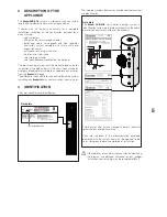
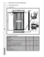
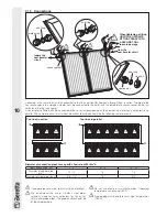
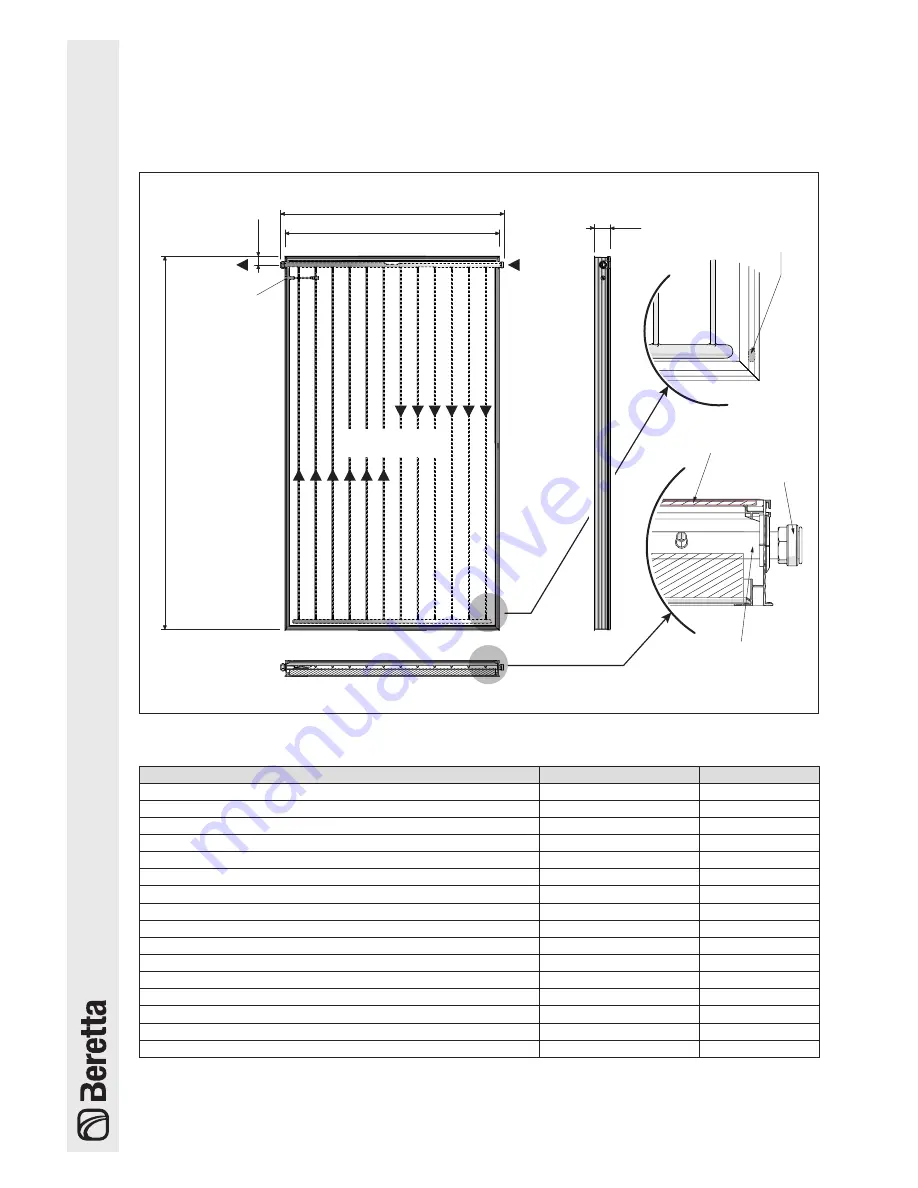
7 .1 .1 System layout
Direction of flow of
heat transfer liquid
Connector Ø 22 mm
Glass
3,2 mm
Connection
ring nut, 1"
85
Collector
outlet
Collector
return
Ventilation holes
Collector
probe socket
1195
1144
2003
46,5
7 .1 .2 Technical specifications
DESCRIPTION
Total area
2,30
m
2
Exposed area
2,16
m
2
Effective absorption area
2,15
m
2
Connections (M) - (F)
1"
mm
Empty weight
40,0
kg
Liquid content
1,6
l
Recommended flow rate for each line per m
2
of collector
30
l/(h x m
2
)
Minimum flow rate for each line per m
2
of collector
12
l/(h x m
2
)
Maximum flow rate for each line per m
2
of collector
60
l/(h x m
2
)
Glass thickness
3,2
mm
Thickness of rock wool insulation
40
mm
Absorption (
α
)
95
%
Emissions (
ε
)
4
%
Maximum permitted pressure
10
bar
Stagnation temperature
197
°C
Maximum number of collectors in a line
6
n°


