Berges electronic
•
D–51709 Marienheide-Rodt
•
Tel. 02264/17-0
•
Fax 02264/17126
Operating manual
21.12.98
ACP 3000 — 0.37–15.0
04_GB
24
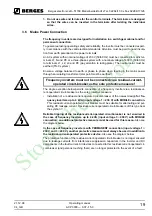
Free-wheeling diodes must be used on contactors, relays and solenoid coils operated with
direct current. The diodes in question should be fast types with short recovery time. The
diode must be connected in blocking direction in parallel with the winding (see Figure 3.2).
The rated current and voltage of the diode can be calculated using the formulae below:
3.9
Function and Use of Terminals
Refer to section 7.1 to 7.7 – Connection Diagrams for power and control wiring examples.
A.
Power Circuit Terminals
Power terminals are located on the power module of the ACP 3000 inverter. They are la-
belled L1, L2, and L3 for incoming three phase AC line power (L1 and N for incoming single-
phase AC line power), and M1, M2, and M3 for the motor connections.
Two ground connections (GND) are provided on the end plate of 0.37 to 4.0 kW IP 21 mod-
els (see Figures 3.4 and 3.5), and along the power terminal strip of 5.5 to 15.0 kW IP 21
models (Figure 3.6). Ground connections can be made to the heat sink on chassis models.
The ground screws must be connected to earth ground in accordance with the NEC.
5.5 to 15.0 kW inverters also have two terminals, B+ and B-, that provide access to the DC
bus rails for the addition of external dynamic braking kits, or extra bus capacitors for custom
applications.
B.
Control Terminals
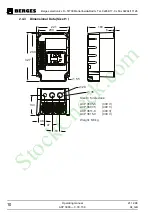
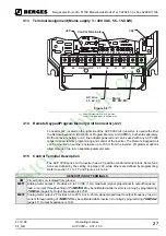
The control terminals are located on the bottom edge of the inverter's control board. See
Figures 3.4 to 3.6, page 26/27 and chapter 3.15. These terminals are available for use with
external devices.
The 20-pole control terminal strip of the units, 0.37–4.0 kW, is plugged in and can be re-
moved in the upward direction to connect the control cables. To do this, place a flat screw-
driver on the metal tabs of the cover securing element and carefully lever off the terminal
strip in the upward direction.
NOTE:
Control input signals must not exceed 24 VDC ±20% potential to ground.
Logic Input Levels:
The input logic is compatible with either 12 or 24 VDC logic. J20 selects active High or Low
control inputs.
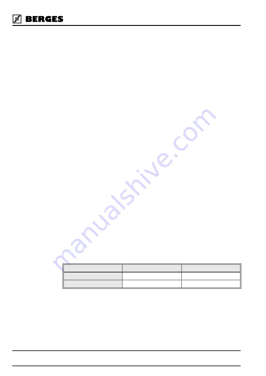
LOGIC TYPE
PULL-UP
PULL-DOWN
Active
10–24 VDC
0–3 VDC
Inactive
0–3 VDC
10–24 VDC
Diode Current Rating (A)
Coil Capacity (VA)
Rated Voltage of Coil (V)
------------------------------------------------------------------
≥
Diode Voltage Rating (V)
Rated Voltage of Coil (V)
2
×
≥
StockCheck.com

