Operating Instructions
09.10.03
Serial Input/Output Converter SIOC03
SIOC03_GB
8
4.6
Biasing an RS-485 Network
When an RS485 network is in an idle state (no communication is being transmitted or re-
ceived), a proper idle voltage state of at least 200 mV must be maintained between the
SIO+ and SIO– lines. The proper idle voltage state must be maintained by selecting the
proper biasing resistors for the network. A 10k ohm pull-up resistor (R2) on the SIO+ line
and a 10k ohm pull down resistor (R20) on the SIO– line do the SIOC03 biasing. When a
terminating resistor is placed between the SIO+ and SIO– lines, however, 10k ohm resis-
tors may not produce enough voltage difference between the SIO+ and SIO– lines to signal
an idle state. As the voltage difference between SIO+ and SIO– increases, the probability
of corrupt communication increases. The SIOC03 provides a method of reducing the bias-
ing resistors to improve communications for the terminated, noisy, or multi-dropped net-
work. Jumpers J18 and J19 place a 1k ohm resistor in parallel with the 10k ohm bias resis-
tors dropping the biasing to 910 ohms. This will increase the voltage difference between the
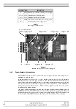
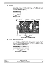
SIO+ and SIO– communication lines. Figure 4 shows the position of the jumpers when the
extra resistance is not added. The SIOC03 also provides a place to add through hole resis-
tors (R49, R50) in parallel to the biasing resistors so that the resistance can be dropped
even further.
5
Operation
5.1
Introduction
This chapter provides information on the operation of the SIOC03 Serial Input/Output Con-
verter.
5.2
Theory of Operation
The SIOC03 module provides a half-duplex (2-wire) RS485 multi-drop connection designed
primarily for use with the BERGES inverter products. All drives on the common RS485 bus
must have their circuit commons (COM or CM terminal) connected. The optical isolation of
the SIOC03 provides an isolation barrier between the drives and the communication host.
This isolation allows baud rates of up to 110 kHz.
When jumper J17 is configured to AUTO, the transmitter for the RS485 is enabled as long
as no activity is detected on the Txd line of the RS232 device. When the SIOC03 detects
the start character of a message it stops all RS485 transmissions so that the RS232 side
can transmit. Because the SIOC03 must detect the activity of the RS232 device, the auto-
matic mode is more susceptible to communication errors than the RTS transmit enable.
This method of conversion, however, is less dependent on host software or operating sys-
tem of the host device.
When jumper J17 is configured to TE, the transmitter for the RS485 is enabled when the
RTS line is low. When the RTS line is high, data on the TxD line is reflected on the RS485
port. A high signal on the TxD line causes current to flow from SIO+ to SIO-. Data on the
RS485 bus is always reflected on the RxD line, regardless of the RTS signal level. All TB
Wood's PC software will work with RTS transmit enable on PCs with Windows 9x systems.
For NT based systems, however, TB Wood's software will require jumper J17 to be config-
ured to AUTO due to restrictions to COM port access in those operating systems.
Handshaking lines RTS and CTS are connected together internally in the SIOC03 module.
No time delay is injected between asserting RTS and receiving CTS.
Handshaking lines DTR, DSR, and DSD are connected together internally in the SIOC03
module. No time delay is injected between asserting DTR and receiving DSR and DCD.
Summary of Contents for SIOC03
Page 1: ...Operating Instructions Serial Input Output Converter SIOC03 ...
Page 2: ......
Page 13: ......


