09.10.03
Operating Instructions
SIOC03_GB
Serial Input/Output Converter SIOC03
5
3.3.2
RS233 Input Connections
The SIOC03 module is provided with a 9 pin “D” shell connector for interface with a PC,
PLC, or other RS232 communication host. Hardware is also provided for securing this con-
nector to the host device. It is strongly suggested that the connector be secured using this
hardware.
If the length of the cable is adequate, and the gender of the connector are correct, the cable
can be plugged directly into the desired communications port (COM Port) of the host de-
vice.
It may be necessary to convert the gender of the 9 pin “D” shell connector. Adapters for this
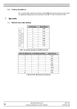
type of conversion are available from third party sources. Details of the signals connected
to the various pins of this connector can be found in section 7.1.
If the communication host has a 25 pin “D” shell connector, an adapter can be made or pur-
chased from a third party. Section 7.1 provides the connection information for such an
adapter.
The length of the input cable assembly can be extended. To do this requires a straight
through cable assembly (i.e pin 1 connects to pin 1; pin 2 to pin 2; etc.). Mouse extension
cables may not perform correctly. To assure reliability, always keep the length of this con-
nection as short as possible, with an absolute maximum of 25 feet. The cable should be
kept clear of any power signals.
3.3.3
RS485 Output Connections
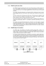
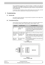
The RS485 output of the SIOC03 is terminated at COM, terminals SIO+ and SIO–. The
proper connection of these terminals, when connected to BERGES inverter products, is
shown in figure 2. Refer to the equipment manual for other devices that you may wish to
connect to the same system for correct connection.
It is strongly recommended that these connections be made with a shielded twisted pair.
The SIO+ and SIO– conductors are twisted. The shield is connected to the common of ei-
ther the SIOC03 module or the device that it is communicating with; but not at both ends.
The end not connected should be taped back to the jacket of the cable. This is the case for
each connection, as shown in figure 2.
Figure 2
Typical RS485 Connections
Summary of Contents for SIOC03
Page 1: ...Operating Instructions Serial Input Output Converter SIOC03 ...
Page 2: ......
Page 13: ......


