Operating Instructions
09.10.03
Serial Input/Output Converter SIOC03
SIOC03_GB
6
4
Configuration
4.1
Introduction
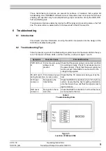
This chapter provides information on setting the configuration jumpers in the SIOC03 mod-
ule.
4.2
Gaining Access to the Configuration Jumpers
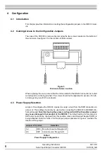
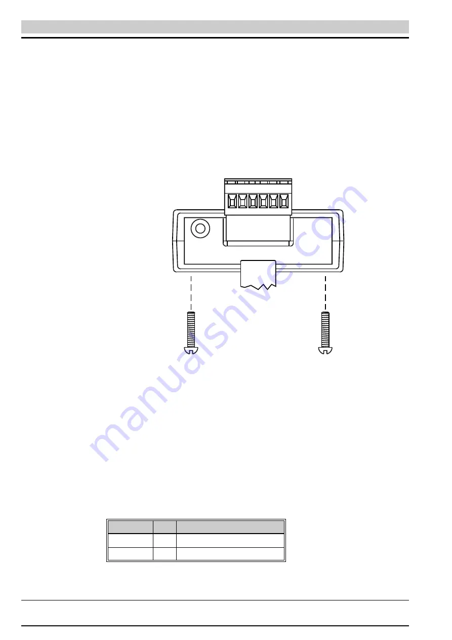
The case of the SIOC03 is removed by removing the two screws located on the bottom of
the enclosure. See figure 3 for the location of these screws.
When replacing the cover, assure that the ribbon cable for the RS232 connection is routed
correctly and is not being pinched. The screws should not be tightened in excess of 6 in-lb,
or damage may result to the enclosure.
4.3
Power Supply Selection
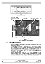
Jumper J16 configures the SIOC03 module to supply current from the PWR connection on
jumper J2. This setting should only be used when connecting the SIOC03 to BERGES En-
hanced Keypad. Note that having the jumper configured to EKP with another product
may cause damage to that product or the SIOC03. The default setting for this jumper is
DRV and should not be changed from this position unless an Enhanced Keypad (EKP) is
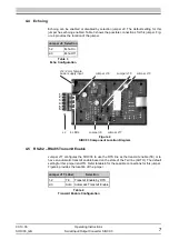
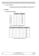
being reflashed. Refer to Table 2 for the proper jumper placement. Figure 4 provides the
location of the jumper.
Figure 3
Enclosure Screw Location
Jumper J16 Label
Selection
1-2
DRV
No current source through J2-1
2-3
EKP
Current source through J2-1
Table 2
Power Supply Configuration
Summary of Contents for SIOC03
Page 1: ...Operating Instructions Serial Input Output Converter SIOC03 ...
Page 2: ......
Page 13: ......


