background image

09.10.03

Operating Instructions

SIOC03_GB

Serial Input/Output Converter SIOC03

7

4.4

Echoing

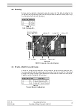
Echoing can be enabled or disabled by selection jumper J9. The default setting for this
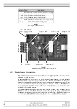
jumper has echoing enabled. Table 3 shows the possible connections for this jumper. Fig-
ure 4 provides the location of the jumper.

4.5

RS232 – RS485 Transmit Enable

Jumper J17 configures the SIOC03 to use the RTS line as the transmit enable (TE) or to
have an automatic transmit enable based on the state of the Txd line (AUTO.) The default
setting for this jumper is AUTO. Refer to table 4 for the possible connections for this jumper.
Figure 4 provides the location of the jumper.

Jumper J9 Selection

1-2

Echo On

2-3

Echo Off

Table 3

Echo Configuration

Figure 4

SIOC03 Component Location Diagram

Jumper J17 Label

Selection

1-2

TE

Transmit Enable by RTS

2-3

Auto

Automatic Transmit Enable

Table 4

Transmit Enable Configuration

J12;

2 mm female

power supply input

Jumper J16

Jumper J18

Jumper J19

Jumper J17

Jumper J9

4 LEDs

J2

1

2

3

4

5

6

Summary of Contents for SIOC03

Page 1: ...Operating Instructions Serial Input Output Converter SIOC03 ...

Page 2: ......

Page 3: ...ons for Control Wiring 3 3 2 3 RS232 Communication Cable 3 3 3 Terminals Found on the SIOC03 3 3 3 1 Power Supply Connections 4 3 3 2 RS233 Input Connections 5 3 3 3 RS485 Output Connections 5 4 Configuration 6 4 1 Introduction 6 4 2 Gaining Access to the Configuration Jumpers 6 4 3 Power Supply Selection 6 4 4 Echoing 7 4 5 RS232 RS485 Transmit Enable 7 4 6 Biasing an RS 485 Network 8 5 Operation...

Page 4: ...nts Report any shipping damage to your nearest BERGES representative 2 2 Product Features Specifications Power supply requirements 5 VDC or 12 24 VDC 50 mA Module input RS232 for PC or PLC 9 pin D shell female Module output RS485 half duplex to terminal block Maximum baud rate 110 k bits per second bps Signal Isolation Optical 1 000 volts Rectified power supply input Power supply polarity makes no...

Page 5: ...is low voltage wiring as follows 1 Shielded wire is recommended to prevent electrical noise interference from causing im proper operation or nuisance tripping Connect the shield as recommended by the equipment manufacturer 2 Twisted pairs are recommended The SIO and SIO conductors should be twisted to gether If a twisted pair is used for the power supply connection the positive voltage and common ...

Page 6: ...lies can also be used and are connected in the same manner The power supply requirement can also be met using a power supply adapter such as BERGES part number PA24DC Such a device must be capable of supplying 24 VDC and capable of supplying 50 mA of current Power from these devices can be connected to the J12 connector of the SIOC03 module See figure 1 for the location of this connector Terminal ...

Page 7: ...n information for such an adapter The length of the input cable assembly can be extended To do this requires a straight through cable assembly i e pin 1 connects to pin 1 pin 2 to pin 2 etc Mouse extension cables may not perform correctly To assure reliability always keep the length of this con nection as short as possible with an absolute maximum of 25 feet The cable should be kept clear of any p...

Page 8: ...f 6 in lb or damage may result to the enclosure 4 3 Power Supply Selection Jumper J16 configures the SIOC03 module to supply current from the PWR connection on jumper J2 This setting should only be used when connecting the SIOC03 to BERGES En hanced Keypad Note that having the jumper configured to EKP with another product may cause damage to that product or the SIOC03 The default setting for this ...

Page 9: ...ansmit enable TE or to have an automatic transmit enable based on the state of the Txd line AUTO The default setting for this jumper is AUTO Refer to table 4 for the possible connections for this jumper Figure 4 provides the location of the jumper Jumper J9 Selection 1 2 Echo On 2 3 Echo Off Table 3 Echo Configuration Figure 4 SIOC03 Component Location Diagram Jumper J17 Label Selection 1 2 TE Tra...

Page 10: ... 2 wire RS485 multi drop connection designed primarily for use with the BERGES inverter products All drives on the common RS485 bus must have their circuit commons COM or CM terminal connected The optical isolation of the SIOC03 provides an isolation barrier between the drives and the communication host This isolation allows baud rates of up to 110 kHz When jumper J17 is configured to AUTO the tra...

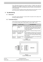
Page 11: ...ased on the status LEDs in the sys tem The location of these LEDs and their function is shown in figure 1 and 5 Symptom Possible Cause Potential Solution PWR LED not lit Correct power supply voltage is not present Check that the power supply is connected and that it is working correctly Check for excessive load on the power supply Check that the power supply se lection jumper in the SIOC2 is set c...

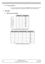
Page 12: ...ntact our Application Engineers can be reached at 49 2264 17 158 or 49 2264 17 160 7 Appendix 7 1 RS232 Connection Details Pin Number Signal Name 1 DCD 2 RxD 3 TxD 4 DTR 5 GND 6 DSR 7 RTS 8 CTS 9 9 Pin D Shell Connections SIOC03 and Host 25 Pin D Shell Host 9 Pin RS232 SIOC03 Signal Name 2 3 TxD 3 2 RxD 4 7 RTS 5 8 CTS 6 6 DSR 7 5 GND 8 1 DCD 20 4 DTR 9 Pin to 25 Pin Serial Port Connections ...

Page 13: ......

Page 14: ...BERGES electronic GmbH Industriestraße 13 D 51709 Marienheide Rodt Postfach 1140 D 51703 Marienheide Tel 0 22 64 17 0 Fax 0 22 64 1 71 26 http www berges de e mail Info_BEL berges de ...

Reviews: