background image


11 

The PowerCenter has a limited current carrying 
capacity so we recommend that you use a DC 
Source Center whenever you have multiple XL.1 
wind turbines.  DC Source Centers are available 
from Bergey Windpower. 
 
Additional Design Guidance: 
 

1.  If you have multiple XL.1 turbines and 

PowerCenters, do not connect more than 
one wind turbine to one PowerCenter. 

2.  Connect multiple PowerCenters to a DC 

Source Center via the PowerCenter’s bat-
tery terminals. 

3.  Do not connect the PowerCenter to an-

other controller that could disconnect the 
PowerCenter from the batteries.  The 
PowerCenter should not be disconnected 
from the battery when there is input from 
the wind turbine.  


B.  Location


The PowerCenter must be installed indoors and 
should be located relatively close to the battery 
bank.  Do not install the PowerCenter outdoors; it 
is not waterproof. 
 

C.  Mounting:


The PowerCenter needs to be mounted vertically 
to a wall, or other support structure, so that air can 
pass unobstructed through the passive cooling 
channel behind the enclosure.  We recommend 
setting the height of the LED’s at eye level if pos-
sible so that the system status lights will be easi-
est to read.  
 
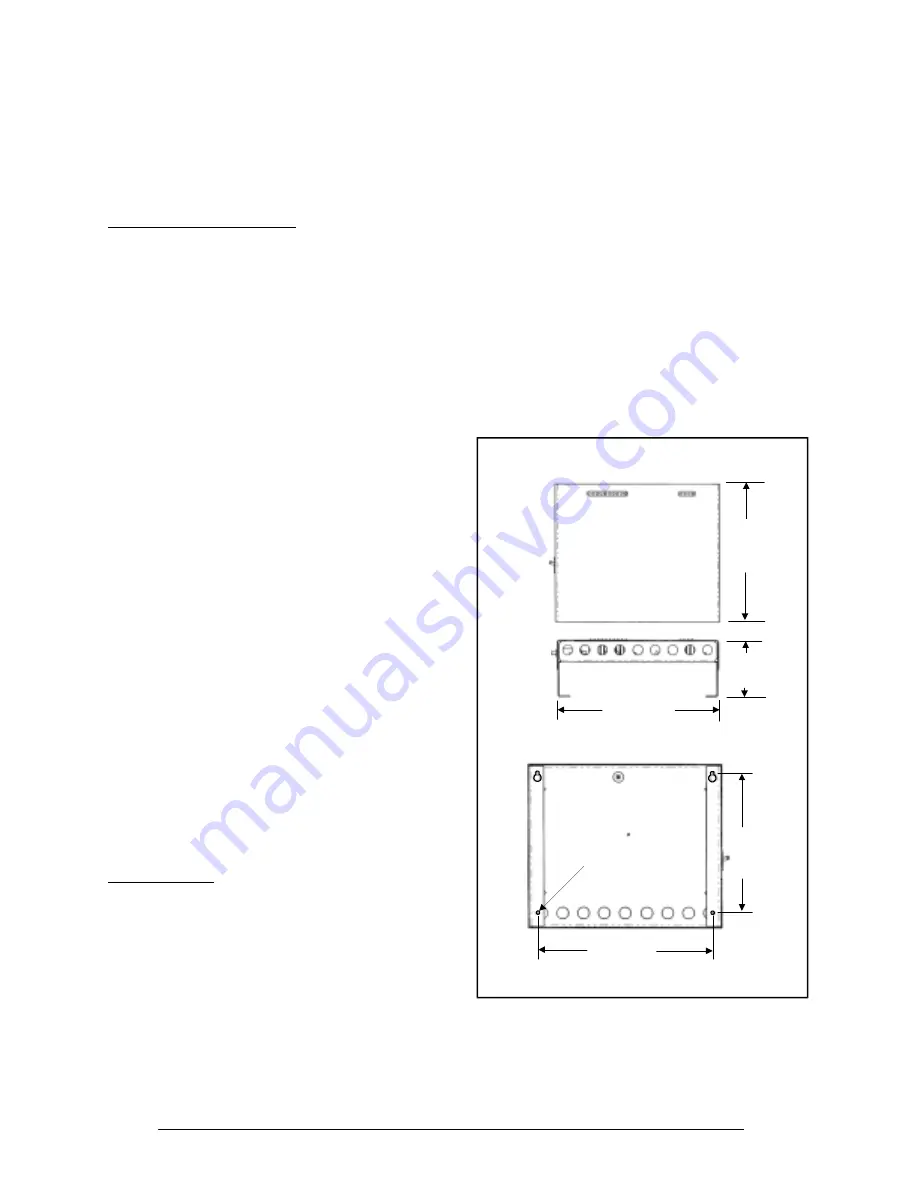
The enclosure dimensions and mounting layout 
for the PowerCenter are shown in Figure 12.  The 
PowerCenter should be mounted with four M4 
(0.157” dia.) screws.  We recommend the follow-
ing procedure: 
 
Tools Required: 
 Pencil 
 Carpenters 

level 


Drill with ~ 2 mm or 0.09” dia. drill bit 


(4) M4, 1/8”, or 5/32” screws 

 Screwdriver 
 
Procedure: 
 

Step 1: 

Mark the mounting hole locations using the Pow-
erCenter enclosure as the template.  Use a car-

penters level to check the levelness of the enclo-
sure before marking the holes.   
 

Step 2: 

Drill small (~ 2.5 mm or 0.1 in diameter) pilot holes 
for the mounting screws. 
 

Step 3: 

Screw the top two mounting fasteners into the wall 
until ~ 6 mm (1/4”) of the shank extends out from 
the wall. 
  

Step 4: 

Remove the PowerCenter cover and place the 
PowerCenter enclosure on the two upper mount-
ing fasteners.  Slide the enclosure down such that 
the fasteners are placed at the top of the inverted 
“T-slots”. 
 

Figure 12, PowerCenter Mounting Dimensions

390 mm
15 3/8“
15.375“

128 mm
5.0“

337 mm
13 1/4“
13.25“

Bottom View

Front View

Enclosure Dimensions

267 mm
10 1/2“
10.5“

333 mm
13 1/8“
13.125“

3.8 mm
0.150“
Diameter
4 Places

Mounting Hole Layout

Equalize Button

Back View


Step 5: 

Install the bottom two mounting fasteners, and 
then tighten the top two fasteners. 

Summary of Contents for 24 VDC B

Page 1: ...ners Manual Owners Manual Owners Manual Owners Manual Bergey Windpower Co Inc 2001 Priestley Ave Norman OK 73069 USA Telephone 405 364 4212 Fax 405 364 2078 E mail sales bergey com Web www bergey com XL 1 Wind Turbine PowerCenter Controller Version 1 1 January 2001 ...

Page 2: ...anual We are particularly interested in learning of mistakes or omissions and subjects that are unclear Please call fax or e mail and direct your comments to Steve Wilke in Customer Service Thank you very much for your assistance Tel 866 237 4397 toll free in U S Tel 405 364 4212 Fax 405 364 2078 e mail swilke bergey com ...

Page 3: ...speed performance very high system effi ciency and low noise The PowerCenter features a solar regulator a dump load capability an automated equalization function and special cir cuitry to boost the low wind speed performance of the XL 1 wind turbine The BWC XL 1 24 is offered with the optional guyed tubular Tilt Tower which comes in heights from 9 m 30 ft to 32 m 104 ft The Tilt Tower is shown in ...

Page 4: ... Windpower The fiberglass blades are exceptionally strong because they are densely packed with glass reinforcing fibers that run the full length of the blade The rotor has three blades because three blades will run much smoother than rotors with two blades Blades Tail Boom Tail Fin Powerhead Alternator Tower Mount Spinner Figure 2 Major Components of the XL 1 Wind Turbine Nacelle B Alternator The ...

Page 5: ...nter The PowerCenter shown in Figure 3 serves as the central connection point for the electrical com ponents in the system and it provides a number of necessary and valuable control functions Not all of the available functions will be used in all instal lations The PowerCenter also provides status lights for the system and a handy light bar fuel gage for the battery bank Note The XL 1 wind turbine...

Page 6: ...s in the systems are carefully bal anced so that at 12 5 m s 28 mph the rotor force acting on the yaw offset is large enough to overcome the preset force holding the tail straight At this point the rotor will start turning away from the wind or furling The tail stays aligned with the wind direction The speed of furling depends on the severity of the wind gusts and whether the wind turbine stays fu...

Page 7: ... which act like a fuel gage for the re mote power system This gage however is inex act and it is intended to provide only a general indication of the energy reserves available in the system The following table shows the voltage indicated by the highest lit LED and its approxi mate relationship to the battery capacity available LED No from left side Indicated Battery Voltage Range Approxi mate Bat ...

Page 8: ... the batteries If the battery voltage rises above 28 VDC the solar is switched off At 29 5 VDC the Extra Load dump load circuit is turned on At 30 5 VDC the wind turbine is turned off As the battery voltage decreases back down to 28 VDC the wind turbine is turned on and the Extra Load is turned off At 27 VDC the solar is turned back on When the equalization function is activated all voltage set po...

Page 9: ...he ground to provide room to assemble the XL 1 turbine We recommend fashioning a temporary support stand to hold the tower up during turbine assembly Step 3 Mount the wind turbine tower adapter to the top of the tower using the six M10 x 1 5 bolts and six washers We strongly recommend applying Loc tite 242 Thread Locking Compound to the threads prior to installation to reduce the likelihood of loo...

Page 10: ...tail fin to the tail boom using the eight M5 bolts and lock washers provided as shown in Figure 9 We recommend applying Loctite to the bolt threads prior to assembly Step 8 Place the tail boom on the rear of the turbine powerhead and insert the 12 mm 1 2 tail pivot pin from the top If the parts are aligned properly the pin should insert easily Do not use a hammer to pound the pin in place as this ...

Page 11: ...e improperly using a gin pole to install a small wind turbine though not a Ber gey turbine Where possible we recommend the first general procedure because it allows work to be done more safely on the ground In this case please follow the general procedure for turbine assembly provided in the preceding section When raising the tower you must lift the tower not the XL 1 wind turbine The XL 1 cannot ...

Page 12: ...so that the system status lights will be easi est to read The enclosure dimensions and mounting layout for the PowerCenter are shown in Figure 12 The PowerCenter should be mounted with four M4 0 157 dia screws We recommend the follow ing procedure Tools Required Pencil Carpenters level Drill with 2 mm or 0 09 dia drill bit 4 M4 1 8 or 5 32 screws Screwdriver Procedure Step 1 Mark the mounting hole...

Page 13: ...bus D PowerCenter Connections Cable Entrances As shown in Figure 13 wiring can be connected to the PowerCenter from below or behind or in a combination of both A total of eighteen 7 8 M20 entrance holes are pro vided Box Lugs The PowerCenter is supplied with box lugs not shown in Figures 12 and 13 that are used to connect electrical leads to the terminals on the PowerCenter circuit board These lug...

Page 14: ...nverter If the system includes a DC to AC inverter connect the inverter input leads to the battery terminals or DC source center not to the PowerCenter The PowerCenter circuit board is not designed to handle the high currents that are possible with inverters Step 7 Connect Loads If the system includes 24 VDC loads connect them to the battery terminals or DC source center Step 8 Reinstall the cover...

Page 15: ...ticularly all electrical connections 15 Check condition of all wiring connections into and out of the PowerCenter Warning Only qualified personnel with proper safety equipment should climb the tower Never climb the tower when the rotor is turning Preventive Maintenance We recommend that the bearings be re packed re greased every 8 12 years There are four tapered roller bearings two for the alterna...

Page 16: ...e Batteries do not reach full state of charge PowerCenter regulating voltage set too low Use hydrometer to check the specific grav ity of the battery cells Compare with battery manufacturer s recom mendation Contact the BWC Ser vice Department for the voltage regulation set point adjustment proce dure Loads are too large Remove largest load If battery bank reaches higher state of charge then the s...

Page 17: ... as it spins Blade tips not evenly spaced Check tip to tip dis tances with a tape measure They should be within 6 5 mm Loosening one blade at a time adjust the tip spacing to bring dis tances within specifica tions Ice build up on blades Visual inspection Se vere icing is very obvi ous Take no action Do not stand under machine The ice will be shed when there is sufficient sun and wind Wind is high...

Page 18: ... Normal operation PV hooked up back wards Check polarity Reverse leads PV fuse blown Check fuse with VOM Replace fuse Dump load does not work Fuse blown Check fuse with VOM Check resistance of dump load should be no less than 1 ohm Replace fuse Voltage below regula tion Check battery bank voltage with VOM If it is below 28 29 5 VDC the dump load should not be coming on Normal operation ...

Page 19: ...18 Appendices ...

Page 20: ...s possible Bergey Windpower Co has experience in working with customers and BWC dealers in variance hearings and we offer advice and assistance to those who request it Generally in order to obtain a building permit you will be required to submit a plot plan and fill out an application A plot plan is a map drawn to scale of your property showing the boundaries dwell ing s and other structures major...

Page 21: ...ne must be placed on a tower that is tall enough to give the rotor proper exposure to the wind Putting a wind turbine on a tower that is too short is like installing a solar sys tem in the shade As a rule of thumb the BWC XL 1 should be 9 m 30 ft above obstacles within 50 m 160 ft particularly in the prevailing wind direction So the minimum recommended tower height is 9 m 30 ft Tower Height meters...

Page 22: ...meters 330 ft if buried or 200 meters 650 ft if in stalled overhead should be avoided because of their high costs On the BWC XL 1 it is not possible to use transformers to increase the wire run voltage because the wire run is direct current DC Transformers only work with al ternating current AC 4 General convenience Often the most compelling consideration for locating the wind turbine tower is the...

Page 23: ...lace though not necessarily permanently affixed We recommend that you leave at least 30 cm 12 in of free wire at the top of the tower for making the electrical connections to the wind turbine E Other System Components A complete remote power system will include other electrical components such as a solar array optional a battery bank required a dump load optional and an inverter optional These com...

Page 24: ...sev eral smaller ones Setting high voltage regulation points too low so that the batteries don t get fully charged Setting the low voltage disconnect typi cally part of the inverter too high so that the battery bank capacity is underutilized ...

Reviews:

Related manuals for 24 VDC B