8
Tilt-up Type Towers:
If you have a tilting
tower, such as the BWC Tilt.Tower, the following
procedure is recommended:
Tools Required:
17 mm box end wrench
17 mm socket and ~ 300 mm (12”) ratchet
drive
8 mm socket or wrench
pliers
crimpers for wiring terminals (U-shaped
crimp preferred over straight crimp)
thread locking compound (like Loctite 242)
tape measure, 12 ft.
Procedure:
Step 1:
With the tower tilted down, place the powerhead
of the wind turbine near the top end of the tower.
The tower wiring is connected to the XL.1 wind
turbine at the slip-ring using two small screws and
ring terminals crimped to the two conductors. Cut
the outer insulation on the wire back about 60 mm
(2.5 in). Strip the insulation off the outer 12 mm
(1/2 in) of each conductor and crimp on the ap-
propriate ring terminals (several sizes are pro-
vided to match possible wire sizes). Attach the
two power conductors to the slip-ring assembly
with the screws provided. The polarities of the
connections are marked. If your conductors are
color-coded we recommend making note of the
colors connected to positive and negative leads.
The slip ring assembly is not designed to support
the weight of the down-tower wire. A strain reliev-
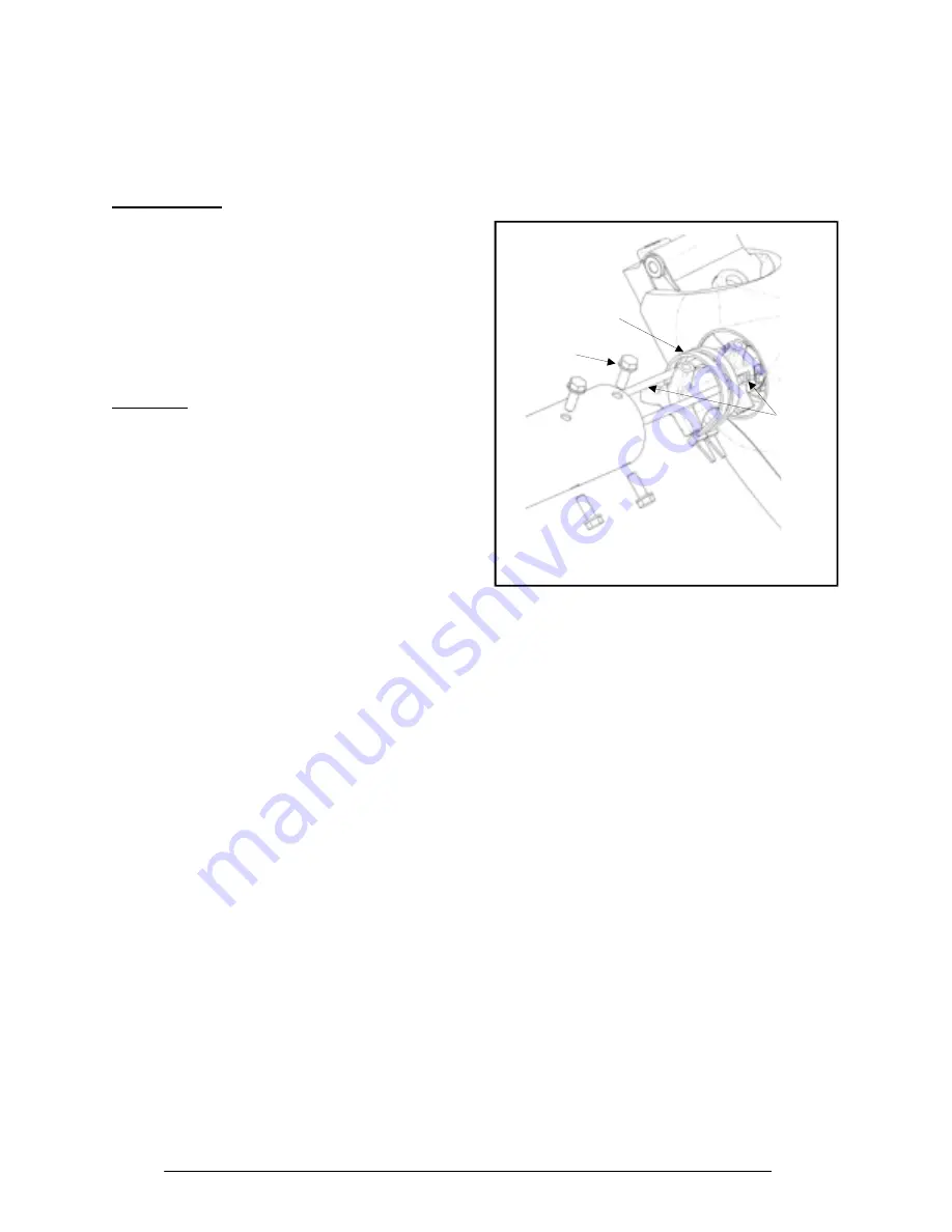
ing installation is required, as shown in Figure 7.
Use the two nylon cable ties provided to secure
the tower wiring to the tower adapter casting. Af-
ter completing the connections, pull on the tower
wire to make sure that it is secure before mount-
ing the wind turbine on the tower.
Step 2:
Raise the tower about 1 meter (3 ft) off the ground
to provide room to assemble the XL.1 turbine. We
recommend fashioning a temporary support stand
to hold the tower up during turbine assembly.
Step 3:
Mount the wind turbine tower adapter to the top of
the tower using the six M10 x 1.5 bolts and six
washers. We strongly recommend applying Loc-
tite 242 (Thread Locking Compound) to the
threads prior to installation to reduce the likelihood
of loosening due to vibration. We recommend
using a torque wrench to achieve the proper fas-
tener torque on the tower mounting bolts. The
recommended toque is 54 N.m (40 ft-lbs).
Power
Cables
Nylon
Cable
Ties
Turbine
Mounting
Bolts
Figure 7, Turbine Mounting
Step 4:
Complete the wiring to the PowerCenter before
adding the blades. This is recommended so that
you can test the DC polarity of the wiring by spin-
ning the alternator by hand. It is very important
that the polarity [positive (+) and negative (-)] is
correct when the turbine is connected to the Pow-
erCenter. The best way to ensure this is to com-
plete the wiring and then test the polarity with a
Volt-Ohm-Meter.
Wiring recommendations are provided in Section
7 and in Appendix 1, section D. Turning the alter-
nator by hand will provide enough voltage to make
this check. Carefully mark the positive and nega-
tive electrical leads for later reference.
Step 5:
Turn the XL.1 powerhead upward so that the al-
ternator is facing up. Attach the blades as shown
in Figure 8 using the M10 hardware provided. We
recommend bolting one blade up solidly and leav-
ing the other two somewhat loose while you check
the tip-to-tip blade distance. We recommend
checking, and adjusting as necessary, the blade
tip spacing to ensure that the blade tips are
equally spaced. This step will help make the wind
Summary of Contents for 24 VDC B
Page 19: ...18 Appendices ...


