background image


PowerSync II 

Operator’s Manual & Installation Instructions 


Page 8 

Rev: 1.1 


1.405.364.4212 

www.bergey.com


5.  Operation 

This  equipment  is  a  UL  1741  certified  Utility  Interactive  Inverter  and  complies  with  the  requirements  of 
IEEE1547 which is the standard for interconnecting distributed resources with electric power systems.  It 
will not operate in an off-grid or backup power configuration. 
 
The  normal  operation  of  the  inverter  is  as  follows:      When  single  phase  utility  power  is  applied  to  the 
output of the inverter, the display will power up and a message stating that the unit is initializing is shown.   
If there are no faults, i.e. grid voltage and frequency are in tolerance, a countdown timer set for 5 minutes 
(300  seconds)  starts  before  the  inverter  is  ready  to  transfer  power  to  the  utility  grid.    The  inverter  will 
automatically  transfer  power  to  the  utility  when  turbine  input  AC  voltages  is  in  the  range  of  30VAC  to 
400VAC. 
 
As the heatsink heats up after exporting significant power for a period of time the internal cooling fans will 
activate.  The inverter is be able to operate at full power continuously if provided with adequate ventilation 
and  the  local  ambient  temperature  stays  below  45ºC  (113ºF).    If  the  ventilation  is  compromised  or  the 
heatsink temperature exceeds 60°C, the inverter will automatically reduce its output power. 

6.  Touch Screen Display 

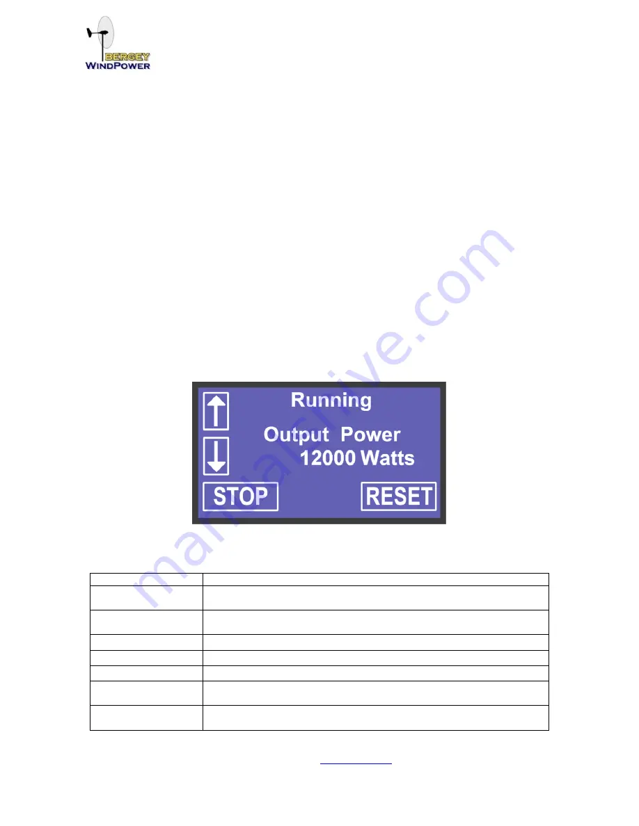
The  touch  screen  display  located  on  the  front  panel  of  the  enclosure  provides  manual  over-ride  and 
status  of  the  inverter’s  operation.    The  touch  screen  display  also  provides  a  Stop  and  a  Reset  button.  
The  Stop  button  is  used  when  it  is  desired  to  disconnect  the  inverter  from  the  power  grid  and  the  wind 
turbine.    After  Stop  is  pressed  the  inverter  will  remain  in  a  powered-up  stand-by  mode  until  Reset  is 
pressed or Grid voltage is removed.  When Reset is pressed the inverter will resume normal operation. 


The status of the inverter

’s operation is shown on the lines one and two of the display. The following table 

lists the status messages that may appear. 
 

Status Message 

Description 

Waiting 

Initializing 

The inverter has been reset or that the 5 minute countdown delay is in 
progress 

Waiting 

For Wind 

The voltage from the turbine is lower than the factory set auto-start 
voltage threshold 

AC Running 

The active rectifier is regulating the internal DC Boost voltage 

Running 

The inverter is transferring power to the utility grid 

Fault 

A fault has occurred.  See fault messages 

Manual Stop 

Press Reset 

The manual stop button has been pressed 

Fault Limit 

Press Reset 

Three faults have occurred in an hours time 

Summary of Contents for POWERSYNC II Series

Page 1: ...ny Manual POWERSYNC II INVERTER Operator s Manual Installation Instructions Part No MANPSII Rev 1 1 November 2014 Bergey WindPower Company All Rights Reserved 2200 Industrial Blvd Norman Ok US 1 405 364 4212 HUwww bergey comU ...

Page 2: ...y 28 2010 CNL Additionally evaluated to CAN CSA C22 2 No 107 1 1 General Use Power Supplies 3rd Edition Dated September 1 st 2001 with revision through 2006 The Bergey WindPower Company s model PSII12 and PSII126208 inverters are intended for variable frequency un rectified 3 phase AC input from Wind Powered Turbines 1 Table of Contents 1 TABLE OF CONTENTS 1 2 RATINGS 2 2 1 INPUT RATING 2 2 2 OUTP...

Page 3: ...120 VAC Operating Voltage Range Line Neutral 106 132 VAC Continuous Output Current Maximum 50 Amps Continuous Output Current Tolerance 10 Voltage Measurement Tolerance 10 VAC Operating Frequency Nominal 60 Hz Operating Frequency Range 59 3 to 60 5 Hz Operating Frequency Measurement Tolerance 0 5 Hz Output Power Factor 0 95 0 05 Temperature Range Normal Operation 4 F to 113ºF 20ºC to 45ºC Output Ov...

Page 4: ...s Use No 4 1 0 AWG 75 C Copper Clad Aluminum or Aluminum Conductors The following symbols are used as markings on this product with the following meanings Equipment grounding conductor This inverter is intended for operation in an indoor NEMA 1 compatible environment having a maximum ambient temperature of 45 C 113 F This unit or system is provided with fixed trip limits and shall not be aggregate...

Page 5: ...PowerSync II Operator s Manual Installation Instructions Page 4 Rev 1 1 1 405 364 4212 www bergey com 4 Installation 4 1 Dimensions ...

Page 6: ...vided with top and bottom venting of at least 100 square inches at each opening 4 3 Mounting The enclosure having a NEMA 1 rating is designed for indoor installation The enclosure is provided with four mounting feet with 7 16 dia mounting holes For mounting to a 0 10 thick metal surface use M6 3 8 bolts grade 3 or higher with nuts and flat washers For mounting to concrete use M6 or 3 8 bolts using...

Page 7: ...ng Terminals o 50 lbf in tightening torque o 8 AWG to a maximum of 2 AWG for Copper Conductors Only o Wire rated 75 C minimum 4 7 Earth Ground Connection Earth ground is to be connected to the two terminals provided inside the enclosure indicated by the earth ground equipment marking o Allowable wire size range is 8 AWG 4 AWG o 50 lbf in tightening torque The inverter s earth ground connections av...

Page 8: ... Input Disconnect Switch With three UL listed 400V 50A fuses Tower Disconnect Switch 240 Vac Utility Connection Reversing Meter For inverter inputs use Isolated 3 phase 600 Vac wire 6 2 AWG 90 C copper wire only 4 AWG minimum recommended 240Vac Split phase connection Surge Arrestor Run the phase wires either inside the tower tube or in grounded metal conduit This helps reduce induced current from ...

Page 9: ...ays below 45ºC 113ºF If the ventilation is compromised or the heatsink temperature exceeds 60 C the inverter will automatically reduce its output power 6 Touch Screen Display The touch screen display located on the front panel of the enclosure provides manual over ride and status of the inverter s operation The touch screen display also provides a Stop and a Reset button The Stop button is used wh...

Page 10: ... over time of operation VREF Used for factory installer setup IREF Used for factory installer setup Last Fault Displays the last fault that occurred since the inverter was powered up along with a fault code that may be useful when troubleshooting Unit Code Rev Indicates the firmware revision of the control DSP Disp Code Rev Indicates the firmware revision of the LCD display DSP A hidden feature of...

Page 11: ...age tracked by VREF Using this configuration the inverter can be adjusted to provide any power curve required IREF Idc 9 Last Fault Fault messages are displayed when a fault occurs and when the last fault parameter is selected The following table is a list of possible faults that may be displayed 7 Trouble Shooting Fault Message Fault Code Description INTERNAL ERROR 10 IGBT or control logic fault ...

Page 12: ...eeded Check for obstructions in the intake bottom and exhaust vents both sides cooling fans are both working proper ventilation is provided and no exposure to direct sunlight UNDER TEMP 4250 The internal low temperature threshold has been exceeded Avoid exposing the unit to temperatures below 20ºC 68ºF GROUND FAULT 7000 A grid side phase is shorted to chassis ground It may require a a Megger to tr...

Page 13: ...e product should be returned in its original shipping materials Unapproved containers may cause further damage to your inverter Contact BWC if replacement material is required Seal the carton securely and ship prepaid to the following address with the RMA number on the label Be sure to insure your inverter with your shipper Bergey WindPower Company Service Department 2200 Industrial Blvd Norman OK...

Reviews: