USER MANUAL 1.2 | B-FORTIS CC-SLIM SERIES
Berghof Automation GmbH | Arbachtalstrasse 26 | 72800 Eningen | Germany | www.berghof-automation.com
23
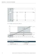
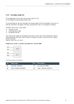
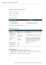
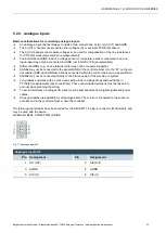
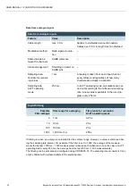
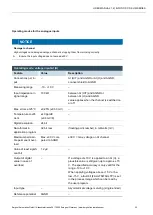
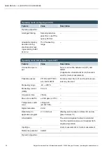
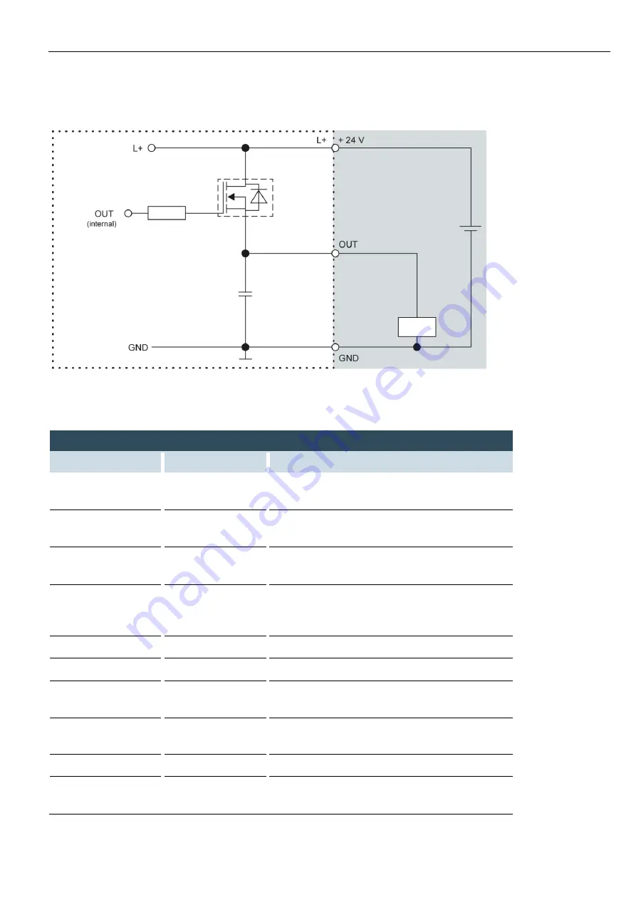
Fig. 6: Circuit diagram of the principles of positive switching, output
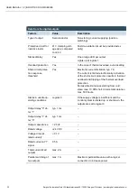
Data from the digital inputs
Feature
Value
Description
Type of input
Type 1, 3
Acc. to IEC 61131-2
Current consuming (positive switching)
Cable length
max. 30 m
For unshielded connection cables
Cables over 30 m in length must be shielded.
Cable cross-section
in the control cabinet
0.14
–1.5 mm²
(26-16 AWG)
Aim for plug connector limits to UL specifica-
tions.
Field wiring
comply with regu-
lations and stand-
ards
Comply with all applicable local regulations and
the requirements of DIN EN 61131-2.
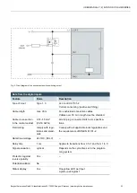
Rated load voltage
24 V DC (SELV)
–
Delay time
1 ms
Applies to transitions from 0 to 1 and from 1 to 0
Signal evaluation
cyclical
Depends on the cycle time set in the program-
ming system
Protection against
reverse polarity
Yes
–
Potential isolation
No
–
Status display
Yes
One yellow LED per input
Lights up at logical 1


