USER MANUAL 1.2 | B-FORTIS CC-SLIM SERIES
Berghof Automation GmbH | Arbachtalstrasse 26 | 72800 Eningen | Germany | www.berghof-automation.com
33
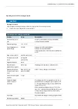
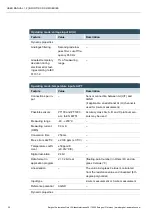
5.2.9. Analogue inputs
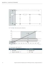
Basic considerations for connecting analogue inputs
→
An analogue input channel always consists of two connections: AI (U) or AI (U/T) and AGND.
→
The AI (U/T) channels can measure either voltages (U) or evaluate PT100(0) sensors.
→
The AI (U) channels can measure voltages or be used for compensation of the line resistances
for PT100(0) measurements (3-wire measurement).
→
The Earth/Ground/GND lead of a voltage sensor or temperature sensor connected to an ana-
logue input may only be connected to AGND (not to GND or PE (equipotential)).
→
Different AGNDs (e.g. on one terminal strip) may not be connected together.
→
AGNDs may not be connected to the general GND of the control cabinet or to the “M” on the con-
trol cabinet (GND and AGND are already connected within the control cabinet via a special filter).
→
AGNDs may not be connected directly to the PE conductor of the machine or system
→
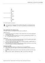
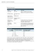
Long cables and wires with a small cross-section lead to voltage drops and deviations in
PT100(0) measurements (due to resistivity). These unavoidable deviations must be taken into
account when planning the wiring.
→
To avoid interference, analogue I/O wires must be kept separate from digital signals and power
cables.
→
Screened cables are advisable for all analogue I/Os. The screen is connected to the sensor or
encoder and in the control cabinet or near the controller.
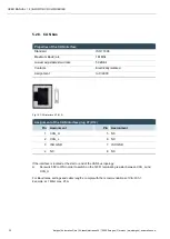
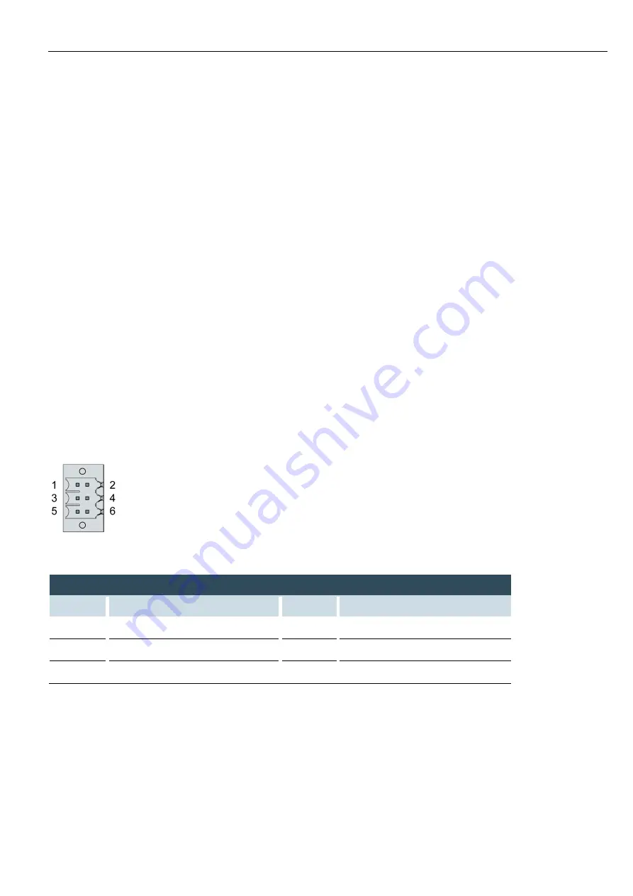
The following counterparts have been tested for the S2C-SMT 3.5 plug-in connector (Weidmüller), and
may be used with the device:
Weidmüller B2CF 3.50/06/180(F) SN BK
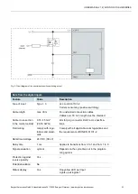
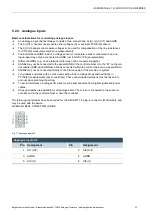
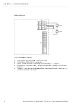
Fig. 17: Analogue inputs X2
Analogue inputs X2
Pin
Assignment
Pin
Assignment
1
AI1 (U/T)
2
AI3 (U/T)
3
AGND
4
AGND
5
AI2 (U)
6
AI4 (U)

