USER MANUAL 1.2 | B-FORTIS CC-SLIM SERIES
Berghof Automation GmbH | Arbachtalstrasse 26 | 72800 Eningen | Germany | www.berghof-automation.com
35
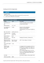
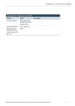
Operating modes for the analogue inputs
NOTICE
Damage to channel
High voltages can damage analogue channels, stopping them from working correctly.
Ensure the input voltage does not exceed ±30 V.
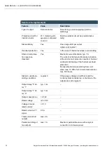
Operating mode: voltage input AI (U)
Feature
Value
Description
Connections per in-
put
–
AI (U/T) and AGND or AI (U) and AGND;
connect shield to AGND.
Measuring range
-10 - +10 V
–
Input impedance in
signal range
100 kΩ
between AI (U/T) and AGND or
between AI (U) and AGND
value applies when the channel is switched on
or off
Max. errors at 25°C
±0.25% (±0.50 mV)
–
Temperature coeffi-
cient
±40 ppm/K
(±0.4 mV/K)
–
Digital resolution
24 bit
–
Data format in
application program
32 bit real
(floating-point number) in millivolts (mV)
Maximum permissi-
ble permanent over-
load
Max. ±30 V com-
pared to AGND
±30 V = max. voltage on AI channel
Value of least signifi-
cant bit
1.2 µV
–
Output of digital
value in case of
overload
–
If a voltage of ±10 V is applied to an AI (U), a
plausible value is still given up to approx. ±15
V. The specified accuracy is only valid for the
range -10 to +10 V.
When applying voltages above +15 V or be-
low -15 V, a fault bit (FAULTN/FAULTP) is set
in the process image which can be read by
the user program.
Input type
–
Asymmetrical voltage metering (single-ended)
Reference potential
AGND
–

