USER MANUAL 1.2 | B-FORTIS CC-SLIM SERIES
Berghof Automation GmbH | Arbachtalstrasse 26 | 72800 Eningen | Germany | www.berghof-automation.com
43
6.3. Operation
6.3.1. Status indicators
The status indicator function is dependent on the software development environment used in conjunc-
tion with the device.
The operating status LEDs show the current status of the power supply, the module mode and any er-
ror messages.
The signals from the LEDs depend on the current operating status of the device:
CODESYS inactive: the firmware controls the LEDs.
CODESYS active: only the CODESYS runtime system (CODESYS Runtime) controls the LEDs.
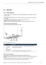
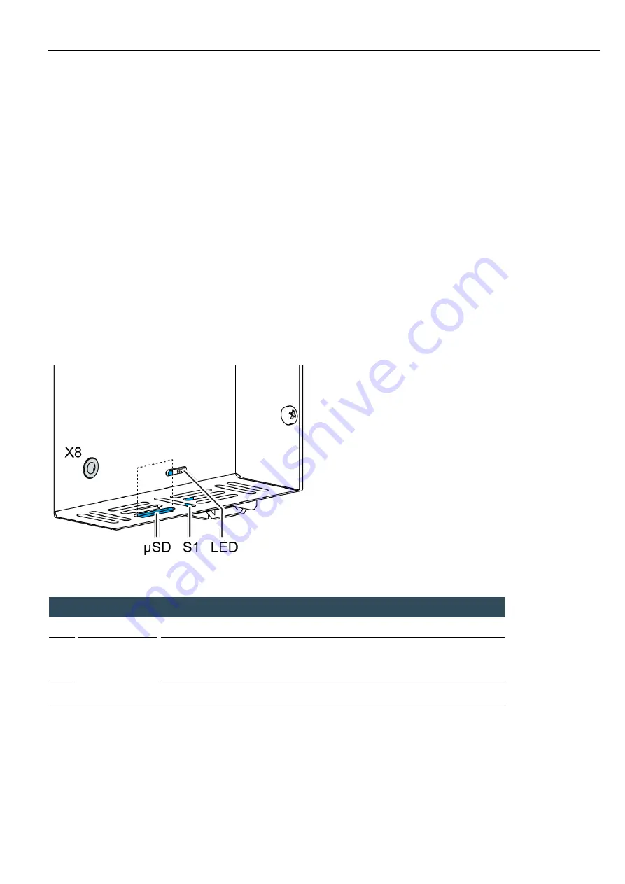
Location of the operating status LEDs
The Run/Stop and Error LEDs display the system status.
Fig. 23: Location of the operating status LEDs
LED
Meaning
1
PWR (green)
Shows that the power supply to the module electronics is correct.
2
Run/Stop
(yel-
low/green/red)
Shows the system statuses.
3
Error (red)
Shows that the device has been stopped due to an error.
Meaning of the LED displays
System statuses are shown using flashing signals on the Run/Stop LED in yellow.
CODESYS operating statuses are shown via continuous illumination of the Run/Stop LED as either red
or green.
While the Run/Stop light is flashing yellow: the device is in use and must not be switched off.
During the boot process, the device does not give any warnings via the LEDs.

