background image


USER MANUAL 1.2 


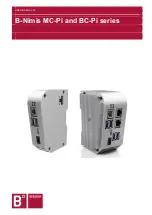
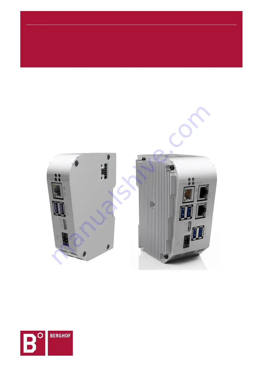
B-Nimis MC-Pi and BC-Pi series 


Summary of Contents for B-Nimis MC-Pi Series

Page 1: ...USER MANUAL 1 2 B Nimis MC Pi and BC Pi series ...

Page 2: ... trademarks of Microsoft Corp in the USA and other countries EtherCAT is a registered trademark and a patented technology licensed by Beckhoff Auto mation GmbH Germany CiA and CANopen are registered community trademarks of CAN in Automation e V ARM and Cortex are registered trademarks of ARM Limited PROFINET is a registered trademark of PROFIBUS Nutzerorganisation e V Modbus is a registered tradem...

Page 3: ...PI SERIES Berghof Automation GmbH Arbachtalstrasse 26 72800 Eningen Germany www berghof automation com 3 Revision log Version Date Description 1 0 16 11 2021 Preliminary version 1 1 06 12 2021 Review version 1 2 17 12 2021 Release Version ...

Page 4: ... 11 1 8 Unpacking 11 2 SAFETY 12 2 1 Safety related systems 12 2 2 Safety instructions 12 2 3 Cyber Security 13 3 PRODUCT DESCRIPTION 14 3 1 Overview 14 4 TECHNICAL DATA 15 4 1 B Nimis BC Pi Pro 15 4 2 B Nimis BC Pi Prime 16 4 3 B Nimis MC Pi Pro 17 4 4 B Nimis MC Pi Prime 18 4 5 Scope of delivery and accessories 19 4 6 Product features 20 5 ASSEMBLY 22 5 1 Installation 22 6 CONNECTION 24 6 1 Powe...

Page 5: ...et button 38 7 4 Troubleshooting 39 7 4 1 No network connection 39 7 4 2 In error stop mode 39 7 4 3 Unknown IP address 39 8 SERVICING MAINTENANCE 40 9 DISASSEMBLY 41 10 DISPOSAL 42 11 INFORMATION AND OPTIONS 43 11 1 Type plate 43 11 2 Device variants and Memory configuration levels 44 11 3 Options and extensions 45 12 STANDARDS AND CERTIFICATES 46 12 1 Standards 46 12 2 Declaration of Conformity ...

Page 6: ...Nimis MC Pi Pro S01 S 01030301 0100 B Nimis MC Pi Pro S02 S 01030301 0200 B Nimis MC Pi Prime S01 S 01030302 0100 B Nimis MC Pi Prime S02 S 01030302 0200 B Nimis BC Pi Pro S01 S 01080101 0100 B Nimis BC Pi Pro S02 S 01080101 0200 B Nimis BC Pi Pro S03 S 01080101 0300 B Nimis BC Pi Prime S01 S 01080102 0100 B Nimis BC Pi Prime S02 S 01080102 0200 B Nimis BC Pi Prime S03 S 01080102 0300 It contains ...

Page 7: ... visual depictions are used in this user handbook Symbol Meaning List entry Individual instruction or list of instructions which can be carried out in any order 1 2 List of instructions which must be carried out in the order given Additional product information Structure of the warnings WARNING Optional More symbols Type and source of the danger Brief description and consequences Preventive measur...

Page 8: ...death or serious injury Take preventive measures CAUTION Possible minor injuries Failure to observe the safety measures may result in minor injuries Take preventive measures NOTICE Possible damage to property Failure to observe the safety measures may result in damage to property Take preventive measures 1 4 Qualified personnel The installation start up and maintenance of the machine must be carri...

Page 9: ...ing in all relevant questions of occu pational health and safety and environmental protection and must be familiar with the con tents of this user handbook particularly the sections containing safety instructions Any markings or identification labels and safety and warning signs on the device must not be removed and must be kept legible at all times The national and international regulations regar...

Page 10: ... qualified project planning proper transport storage installation and use as well as careful maintenance The automation system may only be used within the scope of the information and applications specified in this documentation and associated user handbooks The automation system must only be used as follows As intended In technically perfect condition Without unauthorised modifications By qualifi...

Page 11: ... room temperature of the place of use Wait at least 12 hours after dew has formed before operating the unit 1 8 Unpacking When receiving the unit make sure that the delivery is undamaged and complete Check the packaging for external damage If there is serious damage to the packaging or if damage to the contents is apparent Do not open the packaging any further and inform the carrier and your suppl...

Page 12: ...ystem may result in uncontrolled and or unpredictable operational behaviour All types of failure must be considered at the system level and the associated preventative measures identified If necessary request information from your automation system provider 2 2 Safety instructions The device may only be operated in a flawless condition Exposed sharp edges pose a risk of in jury Working on the devi...

Page 13: ...tion mechanisms this em bedded controller is not designed for this purpose Change the default passwords given at delivery Always use a preceding external firewall so that an external access is prevented Use the security mechanisms of VPN server portals e g IXON to which the controller can actively connect via VPN or comparable mechanisms Use https instead of http Disable the services you do not ne...

Page 14: ... 3 1 Overview Fig 1 Overview of B Nimis MC Pi Prime and BC Pi Prime Fig 2 Overview of B Nimis MC Pi Pro and BC Pi Pro Pos Description Pos Description X1 Power Supply X8 Fan option X2 Display Interface X9 EtherCAT LVDS X3 2 x USB 3 0 X10 2 x USB 3 0 X4 Gbit LAN X11 100 Mbit LAN X5 USB 2 0 Boot X12 100 Mbit LAN X6 Connector for antenna X13 Micro SD X7 Debug S1 Reset ...

Page 15: ...5 1 x EtherCAT LVDS for expansion modules of the B Nimis series WLAN Bluetooth Option Protocol Standard EtherCAT Master Visualization Additional Features 2 x Host USB 3 2 Gen 1 USB Plug Type A 1 x Digital Display Interface 1 x 2 Pin for optional fan 5VDC 1 x Real Time Clock 72h buffer Extended heat sink option Power Supply 24 V DC 20 25 SELV max AC voltage component 5 Reverse polarity protection P...

Page 16: ...0 Base RJ45 1 x Ethernet 10 100 Base 2 Port Switch RJ45 1 x EtherCAT LVDS WLAN Bluetooth Option Protocol EtherCAT Master Visualization Additional Features 4 x Host USB 3 2 Gen 1 USB Plug Type A 1 x Digital Display Interface 1 x µSD SDXC 1 x 2 Pin for optional fan 5VDC 1 x Real Time Clock 72h buffer Extended heat sink option Power Supply 24 V DC 20 25 SELV max AC voltage component 5 Reverse polarit...

Page 17: ... FTP et al Visualization WebVisu WebServer HTML5 using digital display interface integrated web browser or external browser Additional Features 2 x Host USB 3 2 Gen 1 USB Plug Type A 1 x Digital Display Interface 1 x 2 Pin for optional fan 5VDC 1 x Real Time Clock 72h buffer Extended heat sink option EtherCAT Expansion B Nimis MC IO EtherCAT expansion modules DIO AIO Temperature Coun ter Relais Co...

Page 18: ...T BACnet KNX NTP FTP etc al Visualization WebVisu WebServer HTML5 über Digitale Display Schnittstelle integrierter WebBrowser oder externem Browser Additional Features 4 x Host USB 3 2 Gen 1 USB Plug Type A 1 x µSD SDXC 1 x Digital Display Interface 1 x 2 Pin for optional fan 5VDC 1 x Real Time Clock 72h buffer Extended heat sink option EtherCAT Expansion B Nimis MC IO EtherCAT expansion modules D...

Page 19: ... own order number Plug kit MC Pi BC Pi plug kit with 1 x 2 pin plug for the power Order option H001 Order number S 02020201 1000 Additional accessories Antenna Order Option H402 WLAN Bluetooth Dualband Antenna Onmidirectional Order Number S 02050401 0100 WLAN Bluetooth Dualband Antenna screw mount Order Number S 02050401 0200 Fan Order Option H003 Fan 30mm 5V für BC MC Pi Pro Order Number S 020505...

Page 20: ...ction on the side is available The interface is compatible with Berghof modules of the MC I O or E I O series USB The USB 3 2 Gen 1 host interface is a widely used peripheral interface This enables simple data exchange or expansion with compatible USB devices USB sticks with FAT FAT32 exFAT ext3 ext4 formatting are supported For support of other USB devices please contact our technical support Rea...

Page 21: ...CAT LVDS interface with up to 10 nodes on the LVDS bus or max 2 A load 1 x Real time clock RTC buffer time 72h 1 x µSD card slot 1 x display interface 1 x fan connector 5V B Nimis MC Pi Prime S02 S 01030302 0200 1 5 GHz CPU BCM2711 User programme and data memory RAM 2 GB onboard User programme memory eMMC 8 GB onboard 200 KB retain memory only for MC Pi 1x Ethernet 10 100 1000 Base T interface 1x ...

Page 22: ...mounting rail and the mounting surface Press the module at the top against the mounting wall until it snaps into place Fig 3 Installing the B Nimis MC Pi BC Pi NOTICE There must be at least 100 mm clearance above and below the MC Pi BC Pi This guarantees the necessary convection cooling for the MC Pi BC Pi The mounting plate must be made of metal to ensure heat conduction Connecting two modules Af...

Page 23: ...ct from the mod ule to the left of it Push both modules away from one another until they are about 1 cm apart Push the module up and against the metal spring on the lower end of the rail guide Press the module at the top against the mounting wall until it snaps into place Turn the module forwards away from the mounting rail as shown in the illus tration Pull the module down off the mounting rail F...

Page 24: ...uired specifications type K to DIN EN 61131 2 External power supply 24 V DC Supply voltage 24 V DC SELV 15 20 AC voltage component Max 5 the DC voltage level must not fall below 20 4 V Internal power supply A power supply for the system electronics for an input voltage of 24 V DC 15 20 is inte grated into the device The power supply unit has built in reverse polarity protection and surge current p...

Page 25: ...all power supplies including those of connected peripherals B Nimis MC Pi and BC Pi Connect the power supply to the plug according to the following table Power supply plug Connector Pin Function 1 DI digital input 24 V DC 20 25 2 L external power supply 24 V DC 15 20 3 L external power supply GND The following counterparts have been tested for the SL SMT 3 5 plug in connector Weidmüller and may be...

Page 26: ...ic circuit board to the metal housing The metal housing now requires a suitable connection to a functional earth You must ensure that the module housing has a good conductive connection to the top hat rail the top hat rail has a good conductive connection to the control cabinet the control cabinet has a good earthing In special cases the earth wire may be attached straight to the module Fig 5 Eart...

Page 27: ...MC PI AND BC PI SERIES Berghof Automation GmbH Arbachtalstrasse 26 72800 Eningen Germany www berghof automation com 27 6 3 Data connections 6 3 1 Block diagram Fig 6 Block diagram of B Nimis MC Pi BC Pi Fan Voltage Conversion ...

Page 28: ...rding to IEEE 802 3 clause 40 Pin assignment LAN Plug Pin Function Pin Function RJ45 1 D1 5 D3 2 D1 6 D2 3 D2 7 D4 4 D3 8 D4 Status LEDs LEDs LED Color Meaning LED SPEED yellow ON 100 Mbit s 1000 Mbit s Off 10 Mbit s LED LNK RCV green Link Data Receive Blinking connection is active data transfer OFF no connection 6 3 3 USB 3 interface Devices with a USB interface can be connected to the USB host p...

Page 29: ...set This can result in considerable damage to property and damage to the USB device Before using a USB device check its power consumption NOTICE Failures and malfunctions when connected directly to signal ground Only use USB devices that do not have a direct connection between the signal ground and the housing USB thumb drives can be inserted and removed during operation The inserted USB thumb dri...

Page 30: ...ection of the outward and return lines is closed automatically Furthermore the system voltage of the connected I O modules is generated in the MC Pi BC Pi Although this simplifies the connection of the I O modules it must be taken into account with regard to the maximum number of connectable I O modules Additional EtherCAT slaves can be connected to the MC Pi BC Pi with an extender module NOTICE T...

Page 31: ... the device switch off all power supplies including those to any connected peripherals externally powered encoders programming devices etc NOTICE Damage to property Before connecting the power supply ensure that all cabling and the polarity of all the connec tions are correct Switching on The device does not have an on off switch The device starts automatically when the system is switched on or th...

Page 32: ...vice serial number Exception 00 becomes 100 Network mask 255 255 255 0 This setting can be used for initial setup of the device in the IP network NOTICE Damage to property Before connecting the power supply ensure that all cabling and the polarity of all the con nections are correct 1 Supply power to the device 24 V 2 Connect the device to a programming computer using a network cable X4 and networ...

Page 33: ...settings 6 Click on the Network link The Network Configuration page will be displayed Fig 9 Network Configuration page 7 Check the network settings and make any changes in the text boxes if required 8 Save the settings by clicking on Save 9 Additional settings can also be viewed and or modified on the web configuration page e g Sys tem time display resolution TargetVisu ...

Page 34: ...en Germany www berghof automation com 34 In order to accept all of the modified settings reboot the device Briefly disconnect the device from the power supply or Click on Reboot in the web interface and then confirm on the next page by clicking on Reboot Module The device is configured and ready for use ...

Page 35: ...ators Power LED 4 operating status LEDs show the current status of the power supply the module mode and any error messages LED Logical status 1 PWR green ON power supply to the module electronics is correct RUN STOP button Action Command Boot phase Pressing the button Change to maintenance mode CODESYS SPS Short press Change between RUN and STOP mode of the PLC Long press Stop the PLC with RESET o...

Page 36: ...P LED ERROR PPP configuration mode active Yellow Off USB package update active Flashing yellow Off System error Off Red PLC status RUN Green Off STOP Red Off Error stop Red Red Reset detected Flashing red Off Applicative states Identification of ProfiNET device Flashing yellow Flashing Basic procedure for error stop Determine the cause of the fault by reading the web browser Correct the cause of t...

Page 37: ...ng the SD card can result in the device malfunctioning The failure of elec tronic control systems may result in uncontrolled and unpredictable operational behaviour Insert or remove an SD card only when the device is switched off Inserting an SD card 1 Switch the device off 2 Insert the SD card into the SD card slot 3 Switch the device on again The SD card is now ready for data transfer read write...

Page 38: ...tus CODESYS Stop Start Reset A running CODESYS application is stopped by briefly pressing the button The Run Stop LED changes from green to red A second short press will start the CODESYS application The Run Stop LED changes from red to green If the button is pressed and held for more than 5 seconds a Warm reset is triggered After the time has elapsed the Run Stop LED flashes quickly and the butto...

Page 39: ...C Log System Log Correct the cause of the fault Restart the device press Reset on the device also see 6 3 4 Device is ready for use 7 4 3 Unknown IP address If the IP address of the device is unknown a USB update can be carried out to reconfigure it 1 Reboot the device while pressing and holding S1 until the Run Stop LED flashes every 2 sec onds The device is now in maintenance mode and can be rea...

Page 40: ... malfunctions may result in uncontrolled and unpredictable operational behaviour Do not insert connect undo or touch any connections while the device is in operation Before starting any work on the device switch off all power supplies including those to any connected peripherals externally powered encoders programming devices etc If the device is used correctly it should not require maintenance Ma...

Page 41: ...evice can fall down from the top hat rail or get dam aged Do not tilt the device Secure the device to prevent it from falling particularly when removing it from the control cabinet Push the module up and against the metal spring on the lower end of the rail guide Press the module at the top against the mounting wall until it snaps into place Turn the module forwards away from the mounting rail as ...

Page 42: ...options are available for disposal of the device Disposal by the manufacturer Unless otherwise agreed devices can be returned for disposal Disposal in accordance with regional regulations Dismantle the device and disassemble it completely into its component parts Send the metal parts for metal recycling Sort the electronic parts circuit boards drives etc Dispose of electronic scrap in accordance w...

Page 43: ...Fig 12 Type plate Pos Description 1 Product description 2 Order number article number 3 Production date year week 4 Supply voltage and maximum cur rent 5 Manufacturer manufacturer s ad dress 6 QR code identification no 7 Serial number of the unit 8 Version identification 9 CE marking 10 Logo of the manufacturer 11 MAC addresses of the unit 12 Default password 3 1 6 7 10 4 5 8 12 11 2 9 ...

Page 44: ... S02 S 01030301 0200 2 GB RAM 8 GB eMMC B Nimis MC Pi Prime S01 S 01030302 0100 1 GB RAM 8 GB eMMC B Nimis MC Pi Prime S02 S 01030302 0200 2 GB RAM 8 GB eMMC B Nimis BC Pi Pro S01 S 01080101 0100 1 GB RAM 8 GB eMMC B Nimis BC Pi Pro S02 S 01080101 0200 2 GB RAM 8 GB eMMC B Nimis BC Pi Pro S03 S 01080101 0300 4 GB RAM 32 GB eMMC B Nimis BC Pi Prime S01 S 01080102 0100 1 GB RAM 8 GB eMMC B Nimis BC ...

Page 45: ...ype S000 S999 Software options e g field buses H000 H999 Hardware options e g plug kit certifications C000 C999 Customised options e g customised firmware customised front membrane display For more information about the options available for this device please refer to our product cata logue or website The additional features included or installed in each device are listed on the options label Thi...

Page 46: ...requirements and tests EN 61131 2 Industrial Control Equipment 17 Edition 1999 01 28 UL 508 Technical documentation for the assessment of electrical and electronic products with re spect to the restriction of hazardous substances EN 50581 2012 12 2 Declaration of Conformity The declaration of conformity is available on our website https www berghof automation com next to the respective product for...

Page 47: ... 49 7121 894 183 F 49 7121 894 100 email support controls berghof com https www berghof automation com 13 2 Addresses CAN in Automation international manufacturer and user organisation for CAN users in automa tion CAN in Automation e V CiA Am Weichselgarten 26 91058 Erlangen Germany headquarters can cia de www can cia de EtherCAT Technology Group ETG Headquarters Ostendstraße 196 90482 Nürnberg Ge...

Page 48: ...Pi Pro Prime This software is distributed in the hope that it will be useful but WITHOUT ANY WARRANTY without even the implied warranty of MERCHANTABILITY or FITNESS FOR A PARTICULAR PURPOSE See the GNU General Public License for more details Anyone can obtain the source code for these software components from us on a data carrier CD ROM DVD or USB memory stick This offer is valid within three yea...

Page 49: ...Pi Pro 14 Fig 3 Installing the B Nimis MC Pi BC Pi 22 Fig 4 Disconnecting the B Nimis MC Pi BC Pi 23 Fig 5 Earthing 26 Fig 6 Block diagram of B Nimis MC Pi BC Pi 27 Fig 7 Login window 32 Fig 8 List of web interface settings 33 Fig 9 Network Configuration page 33 Fig 10 B Nimis MC Pi BC Pi status indicators 35 Fig 11 Disassembling the B Nimis MC Pi BC Pi 41 Fig 12 Type plate 43 Fig 13 Label for Opt...

Reviews: