USER MANUAL 1.10 | DC1000 DIALOG-CONTROLLER
Berghof Automation GmbH | Harretstrasse 1 | 72800 Eningen | www.berghof.com
2VF100124FE08.docx | DC1000_HB_en_2D0982010ZD00.docx
95
NOTICE
All application and diagnostic data are set up via the CODESYS controller con-
figuration or are provided by the application. Therefore, the diagnostic interface
cannot be used in an application-specific manner.
Termination
The PROFIBUS-MASTER has a linear topology. It must be terminated at both ends. The PROFIBUS-
MASTER module is not equipped with any internal terminating resistors and we therefore recommend the
use of a plug with switchable termination.
Baud rate
The baud rate is set in the CODESYS controller configuration.
GSD file
The PROFIBUS-MASTER module is integrated in the CODESYS controller configuration with a GSD file. As
of Version 1.10.0, this GSD file will be part of the Berghof Target installation package.
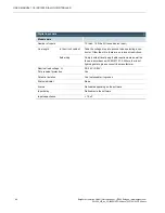
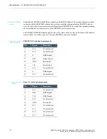
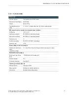
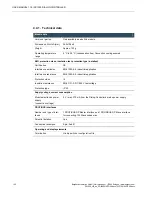
Indicator LEDs
Indica-
tor
Signal
Description
1
Master
Green:
Operating mode
Green, flashing:
Delete mode
Red:
Stop mode
Off:
Offline
2
Database
Green:
Databank OK
Green, flashing:
Database load procedure running
Red:
Database invalid
Off:
No database available
3
Comm.
Green:
Data exchange with all configured slaves
Green, flashing:
Data exchange with at least 1 configured slave
Red:
Bus error, e.g., due to a short circuit or configuration error
Off:
No data exchange
4
Token
Green:
Module has the token
Off:
Token not at the module
All
Red:
Fatal error


