USER HANDBOOK 1.0 | DC2115, ET2115
Berghof Automation GmbH | Harretstrasse 1 | 72800 Eningen | www.berghof.com
21-0099-82-00-00-003 | 270010900_Anwenderhandbuch_DC-ET2115_EN.docx
23
5.1.2. Connecting the power supply to the ET2115
CAUTION
Live parts!
Before starting any work on the device, switch off all power feeds, includ-
ing peripherals.
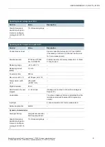
Connect the power supply to connector X100 according to the following table.
Fig. 9: Power supply connector X100
Power supply connector X100
Pin
Designa-
tion
Assignment
9
L0+ 24 V
Power supply 24 V DC (–15 %/+20 %), max. 0.6 A (peak current 1.2 A)
11
GND
M0 / GND
The following counterparts have been tested for the SL-SMT 3.5 (Weidmüller) connector and are approved
for use with the device:
BLZF 3.5/02/180 (F,LR,LH)SN


