-3-
E. The air door is weatherproof. Therefore, no special covering
is required when outdoor mounting unheated, steam, or hot
water units.
NOTE: Electric heated units are to be installed indoors
only.
F.
IMPORTANT:
A minimum of 4” (8” preferred) clearance
is recommended above the top of the air door for the
installation and removal of the screen or to gain access to
junction boxes.
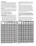
G. When determining the mounting location for the unit(s),
make sure that nothing interferes with the curtain of air
developed when the discharge vanes are directed from 0º
to 20º toward the door opening. If the air stream strikes any
obstruction (the top edge of the doorway, a door opening
device, etc.), the effectiveness of the unit will be greatly
reduced.
See Drawing 1.
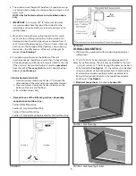
H. For optimum performance, the bottom of the unit
(discharge nozzle) should be no more than 1” above the top
of the door opening with the unit mounted flush to the wall.
If the unit must be mounted higher, it must be
spaced out
from the wall
³/₈” for every inch
the unit is above the door
opening.
See Drawing 2.
I.
Electric heated units shall:
1. Have a minimum clearance of at least 1” between the
sides and top of the unit and any combustible material.
2. Have a minimum clearance of at least 6’ between the
bottom of the unit and the floor.
3. Be installed indoors only.
J.
Proceed to one of the following sections, depending
on application and door type:
Section III: Wall Mounting
Section IV: Suspended Mounting
Section V: Vertical Mounting
Section VI: Tandem Mounting Brackets for Vertical Mounting
DRAWING 1
DRAWING 2
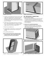
FIGURE 1 - Wall Mounting
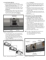
FIGURE 2 - Wall Mounting Bracket
III. WALL MOUNTING
A. Wall mounting works well with standard hinged doors or
sliding doors.
B. The IDC12/IDC14 Series end plates are equipped with ½”
holes for wall mounting. The unit may be attached to the wall
using, at minimum, ³/8” bolts through the holes on the back
of the end plate.
See Figure 1
. Or, the unit may be attached
using an optional wall mounting bracket or a combination
of extension and wall mounting brackets (available from
Berner) attached to the holes on the top of the end plate
and the wall.
See Figure 2
.
C.
Electrical Connections -
Proceed to
Section VII.
EXTERIOR
INTERIOR


