background image

B.  Tandem Mounting Brackets connect the end plates of the 

units to be joined. Two brackets are required. Ideally, the 

units are joined together before the lower unit is bolted to 

the floor.

C.  Using (4) ½ - 13 x 1” bolts, attach the Tandem Mounting 

Brackets to the inside of one of the unit’s end plates as 

shown in 

Figure 8

.

D.  Slide the end plate of the next unit over the brackets 

installed in Step C and attach using (4) additional ½” bolts as 

shown in 

Figure 9

E.   Assemble Floor Mounting Brackets to lower unit and attach 

to floor per steps C and D of Section V. 

F. 

Electrical Connections - 

Proceed to 

Section VII. 

VII. ELECTRICAL CONNECTIONS

All electrical wiring and connections 

MUST

 be performed 

by qualified personnel in accordance with the National

Electrical Code ANSI/NFPA No. 70 (latest edition) or, in Canada,

the Canadian Electrical Code, Part 1-C.S.A. Standard C22.1, and

local codes and regulations.

-4-

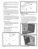
FIGURE 4 - With Extension Brackets

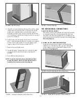
FIGURE 5 - Floor Mounting Brackets

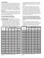
FIGURE 3 - Threaded Rod Suspension

IV. SUSPENDED MOUNTING 

A.  Suspended mounting works well with the majority of door 

types commonly found in an industrial setting, such as roll-

  up doors, “high rise” track doors, “low-rise” turn back doors, 

and “high-rise” turn back doors.

B. The IDC12/IDC14 Series end plates are equipped with ½” 

holes for suspended mounting. The unit may be suspended 

using a minimum ³/8” suspension rod 

(Figure 3)

, or using 

³/8” suspension rods and extension brackets (available from 

Berner). 

 See Figure 4.

C. 

Electrical Connections - 

Proceed to 

Section VII.

V. VERTICAL MOUNTING

A.   Vertical mounting works well when the opening is taller 

than it is wide, or when the door type prevents a typical 

“over-door” mounting position.

B.   Optional Floor Mounting Brackets (available from Berner) 

bolt to the unit end plate, and provide a rigid base to attach 

the unit to the floor. Two Brackets are required.

C.  To vertically mount a IDC12/IDC14 Series unit using optional 

Floor Mounting Brackets, bolt brackets on the inside of the 

end plate with (4) ½ - 13 bolts as shown in 

Figure 5

.

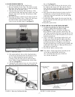
D.  Position the unit vertically in its intended position and 

anchor it to the floor with a minimum ³/8” fastener.  


See


Figure 6

.

E. 

To improve the stability of the installation, it is required 

that the top of the unit be attached to the wall.  A common 

approach is to attach a minimum length of 

³/8”

 threaded rod 

through one of the open mounting holes in the top end 

plate and affix the other end of the rod to the wall.  


See Figure 7

.

F. 

Electrical Connections

 - Proceed to 

Section VII.

VI.  TANDEM MOUNTING BRACKETS

(For Vertical Mount Installation)

A.  Optional Tandem Mounting Brackets (available from Berner) 

are used to join two 

air curtains together in a vertical 

application when the door height exceeds 16’.

Summary of Contents for IDC12 Series

Page 1: ...n in use To avoid burns do not let bare skin touch hot surfaces Keep combustible materials such as furniture pillows bedding papers clothes etc and curtains at least 1 inch from the top back front sides and at least 6 feet from the discharge of the air curtain H Extreme caution is necessary when any air curtain is used by or near children or invalids and whenever the heater is left operating unatt...

Page 2: ... airflow through this void C The air door will not perform properly if negative air pressure exists in the building Under these conditions a means for makeup air to the building must be provided so that the air pressure on both sides of the opening is in balance D Before mounting the air door check the supporting structure to verify that it has sufficient load carrying capacity to support the weig...

Page 3: ...inch the unit is above the door opening See Drawing 2 I Electric heated units shall 1 Have a minimum clearance of at least 1 between the sides and top of the unit and any combustible material 2 Have a minimum clearance of at least 6 between the bottom of the unit and the floor 3 Be installed indoors only J Proceed to one of the following sections depending on application and door type Section III ...

Page 4: ...lates are equipped with holes for suspended mounting The unit may be suspended using a minimum 8 suspension rod Figure 3 or using 8 suspension rods and extension brackets available from Berner See Figure 4 C Electrical Connections Proceed to Section VII V VERTICAL MOUNTING A Vertical mounting works well when the opening is taller than it is wide or when the door type prevents a typical over door m...

Page 5: ... install the Junction Box cover NOTE For electric heated units provided with optional remote thermostat Mount and wire the thermostat according to instructions and wiring diagram VIII MECHANICAL CONNECTIONS A ELECTRIC HEATED MODELS The heater circuit may be controlled by a remote thermostat or manually through the switch located on the discharge side of the unit Overheating protection is provided ...

Page 6: ...r is being directed to both the inside and the outside See Figure 11 The split location is indicated where the handkerchief is vertical with minimal or no fluttering 3 The split location should be approximately 3 outside the doorway If necessary adjust the discharge nozzle vanes by de energizing the unit loosening the nozzle vane locking screws and adjusting vanes X MAINTENANCE AND CLEANING CAUTIO...

Page 7: ... Allen wrench The set screw can be accessed up through the fan discharge or through the small hole on the back of the blower housing 8 Next remove the blower housings by removing the 4 self drilling screws from the back of the fan housing The fan housing and fan impellers may now be slid off of the motor shaft 9 To remove the Motor remove the motor clips from the motors and disconnect the motor gr...

Page 8: ...y expense or liability for repairs made outside its factory without proper written consent from its service manager nor for any transportation charges on apparatus returned to the factory without written authorization by The Company Nothing in the above warranty provisions however shall impose any liability or obligation of any type nature or description upon Berner International if Berner has not...

Reviews: