6
Regulation of burners
Regulation of the "MINIMUM" on the burners
To regulate the minimum on the burners carry out the following procedure indicated below:
1) Turn on the burner and put the knob onto position MINIMUM ( small flame ).
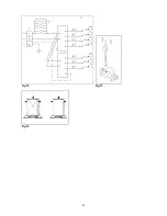
2) Remove the knob ( Fig. 8) of the tap which is set for standard pressure. The knob is found on the bar of
the tap itself.
3) Beside the tap bar on the work top, insert a small slotted screwdriver into the hole on the vale rod (Fig. 8)
and turn the choke screw to the right or left until the flame of the burner is regulated in the most suitable way
to MINIMUM.
4) Make sure that that the flame does not go out when changing the position quickly from MAXIMUM to the
MINIMUM position.
ATTENTION: The regulation described above can be carried out only with burners using natural gas,
while with burners using propane gas the screw must be fully screwed in, in a clockwise direction.
Adaptation of the pressure regulator for use with different type of gas
The pressure regulator supplied with the appliance is a convertible type pressure regulator for use with
Natural Gas at a nominal outlet pressure of 4” w.c. or LP gas at a nominal outlet pressure of 11” w.c. and it is
pre-arranged from the factory to operate with one of these gas/pressure as indicated in the pre-arranging
labels affixed on the appliance, package and Instruction booklet.
To convert the regulator for use with the other gas different from which one it is pre-arranged it is enough
perform the following operations:
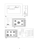
1) Unscrew by hand the upper metal stopper of the regulator (Fig. 5).
2) Unscrew by hand the white plastic piece screwed under the above mentioned metal stopper, afterward
screw it again in opposite way under the metal stopper (for gas reference see the written “LP” and “NAT” with
relative indicating arrows on the white piece).
3) Screw again by hand the metal stopper in the original position on the regulator.
Operating in this way the gas regulator is converted for use with the other gas/pressure.
Descriptions
DESCRIPTIVE CAPTION FOR HOB
DESCRIPTION OF HOBS
1. Small Burner
Model
‘A’
Fig. 9
2. Medium burner
Model
‘B’
Fig. 10
3. Rapid burner
4. Dual burner
5. Front right side of auxiliary burner control knob
6. Front central side of semi-rapid burner control knob
7. Inner dual burner control knob
8. Outer dual burner control knob
9. Rear left side of semi-rapid burner control knob
10. Rear central side of semi-rapid burner control knob
11. Rear right side of rapid burner control knob
12. Front right side of rapid burner control knob
13. Inner dual burner control knob
14. Outer dual burner control knob
15. Rear left side of semi-rapid burner control knob
16. Rear right side of semi-rapid burner control knob
Service & maintenance instructions
Service and maintenance only to be carried out by an authorised person
To replace parts such as burners, valves and electric components, the hotplate must be removed from the
bench top by releasing the attachment hooks, loosening the attachment screws of each burner, unscrewing
the hotplate attachments nuts which are visible at the bottom of the surface, removing the hotplate top and
finally replacing the defective parts.
Note:
if the valves must be replaced, first disassemble the ignitions switches wires.
It is recommended to replace the valve gaskets each time the valve is replaced, thus ensuring a perfect seal
between the body and the gas train.
Summary of Contents for B3W0..U4X2D
Page 20: ...20 Fig 6 Fig 7 Fig 8 Fig 9 Fig 10 Fig 11 ...
Page 21: ...21 Fig 12 Fig 13 Fig 14 ...
Page 23: ......
Page 24: ......
Page 25: ......


