


10
SERVICE & MAINTENANCE INSTRUCTIONS
Service and maintenance only to be carried out by an authorised person
To replace parts such as burners, valves and electric components, the appliance must be open removing the worktop.
Note:
if the valves must be replaced, first disassemble the ignitions switches wires.
It is recommended to replace the valve gaskets each time the valve is replaced, thus ensuring a perfect seal between the
body and the gas train.
WARNING: After first installation of the appliance or after any service intervention concerning main gas parts of
the appliance, make the leak test using water with soap on the gas connections in order to verify the correct
installation. Do not use fire for gas leak testing.
USER MANUAL
DESCRIPTIONS
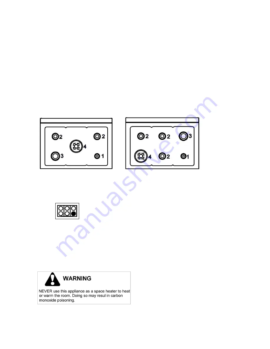
DESCRIPTIVE CAPTION FOR HOB
DESCRIPTION OF HOBS
1. Small Burner
Model C36500X (
Z36 5 00 X
)
[M3W0..U4X(2 or
5)A]Fig. A
2. Medium burner
Model C36600X (
Z36 6 00 X
)
[M3Y0..U4X(2 or
5)A]Fig. B
3. Rapid burner
4. Dual burner
Fig. A
Fig. B
CONTROL PANEL DESCRIPTION
On the control panel, small symbols show the function of each knob or key. Here as follows are the several controls that
a cooker can have:
the symbol
shows the disposition of burners on the worktop, the full dot identifies the burner in object (in
this case the front burner on the right).
WARNINGS:
Keeping appliance area clear and free from combustible materials, gasoline and other flammable vapors and
liquid.
Do not store dangerous or flammable material in the cabinet areas above appliance; store them in a safe place
in order to avoid potential hazards.
For safe use of appliance, do not use it for space heating.
Do not use aerosol sprays in the vicinity of this appliance while it is in operation


