background image


6


Wiring diagram 


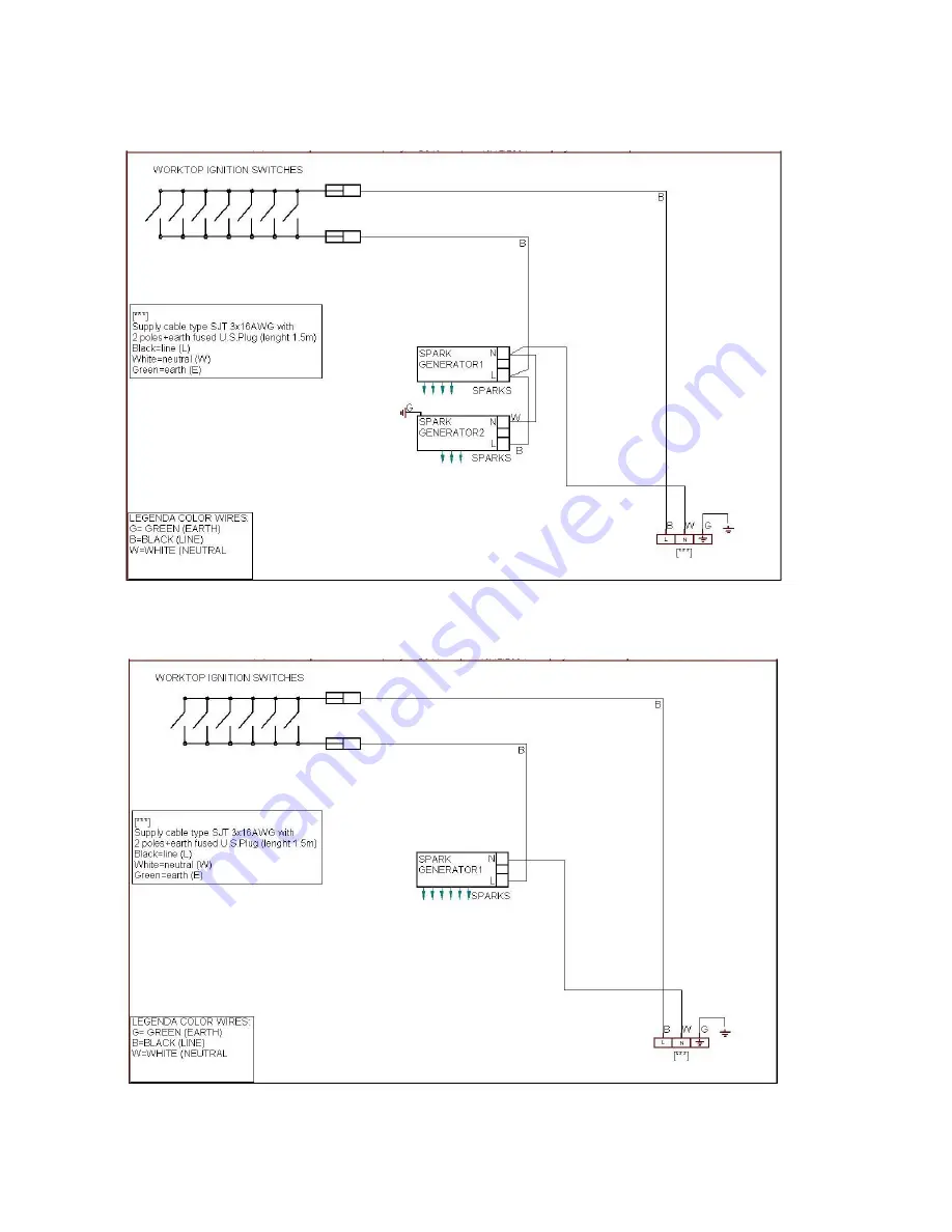
For freestanding gas range model  C36600X (

Z36 6 00 X

)   C3Y0..U4X(2 or 5)A 

CAUTION

: label all wires prior to disconnection when servicing controls. Wiring errors can cause improper 

and dangerous operation. 

Verify proper operation after servicing. 


For freestanding gas range model C36500X (

Z36 5 00 X

)    C3W0..U4X(2 or 5)A 

CAUTION

: label all wires prior to disconnection when servicing controls. Wiring errors can cause improper 

and dangerous operation. 

Verify proper operation after servicing. 


Summary of Contents for C36500X

Page 1: ...Electrical installation must be in accordance with the current CSA C22 1 Canadian Electrical Codes Part 1 and or local codes Installation of any gas fired equipment should be made by a licensed plumber A manual gas shut off valve must be installed in the gas supply line ahead of the oven in the gas flow for safety and ease of service In Massachusetts All gas products must be installed by a Massach...

Page 2: ...he gas supply piping system any pressure testing of that system at test pressure in excess of psi 3 5 kPa The appliance must be isolated from the gas supply piping system by closing its individual manual shutoff valve during any pressure testing of the gas supply piping system at test pressures equal to or less than psi 3 5 kPa For use with a pressure regulator The regulator supplied must be used ...

Page 3: ... the front part of the backguard with the screws supplied with the backguard kit fig 3 4 Assemble back part with front part of backguard and fix them with a screw supplied with the backguard kit fig 4 1 2 3 4 WORKTOP FRONTGUARD INSTALLATION INSTRUCTIONS In order to increase the clearance between front edge of the worktop and the burners for your safety it is recomended to install the worktop front...

Page 4: ...earance to combustible vertical surfaces above 36 91 4 cm I the maximum wall cabinet depth must be 13 33 0 cm and wall cabinets within this 6 15 2 cm side clearance must be 18 45 7 cm above the 36 91 4 cm high countertop 4 4 Wall cabinets above the rangetop must be a minimum of 36 91 4 cm for the open top burner models and a minimum of 42 106 7 cm for the sealed burner models above the rangetop co...

Page 5: ...t be grounded and properly polarized The unit is equipped witth a SJT power cord and in case of replacement the cable shall be replaced with one of the same type size and length WARNING Electrical Grounding Instructions This appliance is equipped with a three prong plug for your protection against shock hazard and should be plugged directly into a properly grounded socket Do not cut or remove the ...

Page 6: ...ing controls Wiring errors can cause improper and dangerous operation Verify proper operation after servicing For freestanding gas range model C36500X Z36 5 00 X C3W0 U4X 2 or 5 A CAUTION label all wires prior to disconnection when servicing controls Wiring errors can cause improper and dangerous operation Verify proper operation after servicing ...

Page 7: ...uring any pressure testing of the gas supply piping system at test pressures equal to or less than 1 2 psig 3 45 kPa 3 Flexible Connections a If the unit is to be installed with flexible couplings and or quick disconnect fittings the installer must use a heavy duty AGA design certified commerciai flexible connector of at least 1 2 1 3 cm ID NPT with suitable strain reliefs in compliance with ANSI ...

Page 8: ... regulator for use with the other gas different from which one it is pre arranged it is enough perform the following operations 1 Unscrew by hand the upper metal stopper of the regulator 2 Unscrew by hand the white plastic piece screwed under the above mentioned metal stopper afterward screw it again in opposite way under the metal stopper for gas reference see the written LP and NAT with relative...

Page 9: ...opane 11 6100 1787 1500 439 0 36 Rapid Rear L 1 55 NG 4 10400 3047 2500 732 Regulated 0 92 LP Propane 11 10400 3047 2500 732 0 47 Centre Inner 0 80 NG 4 2800 820 900 264 Regulated Dual Burner 0 49 LP Propane 11 2800 820 900 264 0 29 Centre Outer N 2 x 1 15 NG 4 12000 3516 4500 1318 Regulated N 2 x 0 70 LP Propane 11 12000 3516 4500 1318 0 65 CAUTION save the orifices removed from the appliance for...

Page 10: ...ONS DESCRIPTIVE CAPTION FOR HOB DESCRIPTION OF HOBS 1 Small Burner Model C36500X Z36 5 00 X M3W0 U4X 2 or 5 A Fig A 2 Medium burner Model C36600X Z36 6 00 X M3Y0 U4X 2 or 5 A Fig B 3 Rapid burner 4 Dual burner Fig A Fig B CONTROL PANEL DESCRIPTION On the control panel small symbols show the function of each knob or key Here as follows are the several controls that a cooker can have the symbol show...

Page 11: ...the burner flame size properly so it does not extend beyond the edge of the cooking utensil This is an instruction based on safety considerations Use suitable pots for each burner see Fig and Table When the liquid is boiling turn down the knob to the MINIMUM position Always use pots with a cover Correct flame aspect verify that aspect flame of the worktop burners be completely blue and with an asp...

Page 12: ... steel parts Clean the parts with soapy water and dry them with a soft cloth The shine is maintained by periodically using specific stainless steel cream cleaner Never use abrasive powders Use specific stainless steel cream cleaner to eliminate the glue remains afther the elimination of the blue plastic protection film on the worktop after installation Cleaning the burner caps Lift the burner caps...

Page 13: ...BURNER PAN SUPPORT 1 1 715 604064 DAISYCHAIN SWITCH 1 715 604065 DAISYCHAIN SWITCH 1 760 510507 SMALL BURNER 1 1 761 510508 SEMI RAPID BURNER 2 3 762 510509 RAPID BURNER 1 1 764 510511 DUAL BURNER 1 1 884 502179 GAS VALVE BY PASS 029 SMALL DUAL INNER 2 2 885 502148 GAS VALVE BY PASS 036 SEMI RAPID 2 3 886 502180 GAS VALVE BY PASS 047 RAPID 1 1 887 502150 GAS VALVE BY PASS 065 DUAL OUTER 1 1 917 20...

Page 14: ......

Page 15: ......

Page 16: ......

Reviews: