background image


15

ELECTRICAL


CONNECTION


The


appliance


shall


be


connected


to


a


single


phase


electric


line


rated


at


120/208Vac


or


120/240Vac


and


60Hz


frequency.


Electric


power


rating:


‐ 

120/208Vac:


4400


Watt


or


21


A


max.


‐ 

120/240Vac:


5500


Watt


or


24


A


max.


Heating


elements


power


rating:


‐ 

Oven


bake


element


=


2100


Watt


‐ 

Oven


circular


element


=


3300


Watt


‐ 

Oven


broil


element


=


3400


Watt


Install


a


suitable


electric


power


supply


receptacle


connection


type


NEMA


14

50R


able


to


support


a


load


of


at


least


30


A


(per


line)


according


to


local


code


requirements.


For


four


or


three


wires


power


supply


connection


system


see


diagram


below.


FOUR-WIRE CONN.RECEPTACLE NEMA 14-50R 


THREE-WIRE CONN.RECEPTACLE NEMA 14-50R 


Check


your


local


code


for


which


of


the


options


below


should


be


used


in


grounding


the


receptacle


power


supply


connections.


OPTION 1 – FOUR Wires connection:  

‐ 

Connect


the


L1


receptacle


terminal


to


the


incoming


BLACK


electrical


supply


wire


(L1

hot


wire)


‐ 

Connect


the


L2


receptacle


terminal


to


the


incoming


RED


electrical


supply


wire


(L2

hot


wire)


‐ 

Connect


the


NEUTRAL


receptacle


terminal


to


the


incoming


NEUTRAL


(WHITE)


electrical


supply


wire


‐ 

Connect


the


GROUND


receptacle


terminal


to


the


incoming


GROUND


(GREEN)


electrical


supply


wire


OPTION 2 - THREE-Wires connection:  

‐ 

Connect


the


L1


receptacle


terminal


to


the


incoming


BLACK


electrical


supply


wire


(L1

hot


wire)


‐ 

Connect


the


L2


receptacle


terminal


to


the


incoming


RED


electrical


supply


wire


(L2

hot


wire)


‐ 

Connect


the


NEUTRAL


with


the


GROUND


receptacle


terminal


to


the


incoming


NEUTRAL


(WHITE)


electrical


supply


wire


DO NOT USE EXTENSION CORDS WITH THIS 
APPLIANCE AS IT MAY RESULT IN FIRE, 
ELECTRIC SHOCK OR OTHER type of 
PERSONAL INJURY. 


The


appliance


is


equipped


at


the


factory


with


an


electric


supply


cord


set


4


wires


type


with


ring


terminals


(L1,


L2,


N,


Ground)


suitable


for


range


use


UL/CSA


listed


type


SRDT/DRT


2x6AWG


(L1,


L2)+2x8AWG


(N,


G)


rated


300V,


40


or


50A


with


fused


plug


type


NEMA


14

50P;


cable


length


1,5


m.;


in


case


the


supply


cord


set


must


be


replaced,


it


shall


be


replaced


with


an


identical


set


having


the


same


technical


specs


and


following


carefully


the


instructions


and


diagrams


below:


1)


Disconnect


appliance


from


electrical


power


supply


receptacle


2)


Slide


out


the


appliance


from


installation


place


to


access


to


back


enclosure


panel


3)


Remove


back


enclosure


panel


by


removing


the


6


screws


as


shown


below


Summary of Contents for MAS30 4 DFS XT

Page 1: ...GES Models PRO30 4 DFS X M7S0PTU7X5DUA Models PRO30 4 DFS AR M7S0PTU7S5DUA Models PRO30 4 DFS BI M7S0PTU7W5DUA Models PRO30 4 DFS NE M7S0PTU7N5DUA Models PRO30 4 DFS RO M7S0PTU7R5DUA Models PRO30 4 DFS VI M7S0PTU7L5DUA Models MAS30 4 DFS XT M7S0PTA7X5DUA 310839 ...

Page 2: ...ur appliances are designed according to the strictest safety and performance standard for the European and the North American market We follow the most advanced manufacturing philosophy Each appliance leaves the factory after thorough quality inspection and testing Our distributors and our service partners are ready to answer any questions you may have regarding how to install use and care for you...

Page 3: ...3 ...

Page 4: ...ION 19 PRESSURE REGULATOR 20 GAS CONVERSION 20 STEP 1 PRESSURE REGULATOR 20 STEP 2 SURFACE BURNERS 21 STEP 3 MINIMUM FLAME ADJUSTMENT 21 GAS BURNERS DATA TABLES 22 INSTALLATION CHECKLIST 23 INSTALLATION CHECKLIST 23 FINAL PREPARATION 23 USER MANUAL 24 ROOM VENTILATION 24 SURFACE BURNER LAYOUT 25 SURFACE COOKING 25 SYMBOLS 25 SURFACE BURNER OPERATION 26 TIPS FOR USING BURNERS CORRECTLY 26 TIPS FOR ...

Page 5: ...30 TURBO 30 RACK POSITIONS 31 BAKING RECOMMENDATIONS 32 WARMING 32 PROOFING 32 DEHYDRATE 33 BROIL CONVECTION BROIL 34 BROILING AND ROASTING RECOMMENDATIONS 35 CARE AND MAINTENANCE 36 SELF CLEANING THE OVEN 36 MAINTAINING YOUR RANGE 37 CLEANING YOUR RANGE 37 TROUBLESHOOTING GUIDE 38 LOCATION OF APPLIANCE TAGS 39 IMPORTANT APPLIANCE INFORMATION 40 ...

Page 6: ...sh hotline 866 905 0010 French 800 561 7625 Fax 714 428 0040 Email BERTAZZONIHELP SERVICEPOWER COM Mailing address SERVICEPOWER 1503 South Coast drive Suite 320 Costa Mesa CA 92626 REPLACEMENT PARTS Only Bertazzoni replacement parts may be used in performing service on the appliance Replacement parts are available from factory authorized parts distributors AP Wagner PHONE 1 888 279 2463 FAX 716 85...

Page 7: ...ny other appliance Installation and service must be performed by a qualified installer service agency or the gas supplier In Massachusetts All gas products must be installed by a Massachusetts licensed plumber or gasfitter A T handle type manual gas valve must be installed in the gas line connected to this appliance WHAT TO DO IF YOU SMELL GAS Do not light any appliance Do not touch any electrical...

Page 8: ...ease observe all local and national codes and ordinances Please ensure the range is properly grounded The installer should leave these instructions with the consumer who should retain for local inspector s use and for future reference The plug should always be accessible Installation must conform with local codes or in the absence of codes the National Fuel Gas Code NSIZ223 1 latest edition Electr...

Page 9: ...drawings front side and back Weight Burner power Natural gas LP gas Auxiliary 3750 BTU h 3750 BTU h Semi rapid 6000 BTU h 6300 BTU h Rapid 10400 BTU h 11400 BTU h Dual burner inner 2730 BTU h 2900 BTU h Dual burner outer 15000 BTU h 16400 BTU h ...

Page 10: ...or and the shutoff valve The appliance must be isolated from the gas supply piping system by closing its individual manual shutoff valve during any pressure testing of the gas supply piping system at test pressures equal to or less than psi 3 5 kPa All opening and holes in the wall and floor back and under the appliance shall be sealed before installation of the appliance A manual valve shall be i...

Page 11: ...he unit Adjust leg height to the desired level by twisting the inside portion of the leg assembly until the proper height is reached Check with a level that the cooktop is perfectly level INSTALLING THE WORKTOP FRONTGUARD To increase the clearance between the front edge of the worktop and the burners it is possible to install the worktop front guard shipped with the appliance To install the front ...

Page 12: ...tal screws for securing the back guard to the worktop Disassemble the back guard and position the front part on the worktop Align the screw holes with the corresponding holes at the back of the worktop If the holes are not aligned partially loosen the brackets at the back of the worktop as shown below Install the front part of the back guard by tightening the 2 central screws from the top and 2 la...
Page 13: ... brackets to the wall with appropriate hardware Slide the range against the wall until the brackets are fully inserted into their receptacles on the back of the range INSTALLATION REQUIREMENTS ELECTRICAL A properly grounded and horizontally mounted electrical receptacle Type NEMA 14 50R should be installed no higher than 3 7 6 cm above the floor no less than 2 5 cm and no more than 8 20 3 cm from ...

Page 14: ...ove the range shall be 13 33 0 cm EXHAUST HOOD INSTALLATION This range will best perform when used with PRO line Bertazzoni exhaust hoods These hoods have been designed to work in conjunction with the Bertazzoni range and have the same finish for a perfect look For maximum performance the height of the bottom of the hood from the worktop should be between 25 1 2 65 cm and 31 1 2 80 cm This would t...

Page 15: ... incoming NEUTRAL WHITE electrical supply wire Connect the GROUND receptacle terminal to the incoming GROUND GREEN electrical supply wire OPTION 2 THREE Wires connection Connect the L1 receptacle terminal to the incoming BLACK electrical supply wire L1 hot wire Connect the L2 receptacle terminal to the incoming RED electrical supply wire L2 hot wire Connect the NEUTRAL with the GROUND receptacle t...

Page 16: ...uitable position 7 Fix well the ring terminals G L1 N L2 of the new supply cord set as shown in diagram with its 4 screws 8 Re install the back enclosure panel with 6 screws 9 Slide the appliance back into its proper location 10 Re connect the appliance to the electrical power ELECTRICAL GROUNDING This appliance is equipped with a four prong plug for your protection against shock hazard and should...

Page 17: ...ll wires prior to disconnecting when servicing controls Wiring errors can cause improper and dangerous operation Verify proper operation after servicing LOCATION OF APPLIANCE PLATES The data rating plate shows the model and serial number of your range It is located under the front edge of the range cooktop and is visible when the oven door is open see illustration A Rating plate s located under fr...

Page 18: ...18 WIRING DIAGRAM ...

Page 19: ...pliance shall be conducted according to the manufacturer s instructions Before placing the oven into operation always check for leaks with soapy water solution or other acceptable method MANUAL SHUT OFF VALVE THIS VALVE IS NOT SHIPPED WITH THE APPLIANCE AND MUST BE SUPPLIED BY THE INSTALLER The manual shut off valve must be installed in the gas service line between the gas hook up on the wall and ...

Page 20: ...ce from gas and electricity Gas conversion shall be conducted by a factory trained professional Call the customer service hotline to identify a factory trained professional near your home The gas conversion procedure for this range includes 6 steps 1 Pressure regulator 2 Surface burners 3 Adjustment of minimum setting The conversion is not completed if all 6 steps have not been concluded properly ...

Page 21: ...JUSTMENT WARNING These adjustments should be made only for use of the appliance with natural gas For use with liquid propane gas the choke screw must be fully turned in a clockwise direction SURFACE BURNERS 1 Light one burner at a time and set the knob to the MINIMUM position small flame 2 Remove the knob 3 The range is equipped with a safety valve Using a small size slotted screwdriver locate the...

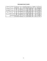
Page 22: ... 264 0 29 Semi Rapid Front R 1 17 NG 4 6000 1759 1500 439 Regulated 0 73 LP Propane 11 6300 1845 1500 439 0 36 Rapid Rear R 1 55 NG 4 10400 3046 2500 732 Regulated 0 98 LP Propane 11 11400 3339 2500 732 0 47 Front L Inner 0 80 NG 4 2730 799 900 264 Regulated Dual Burner 0 50 LP Propane 11 2900 849 900 264 0 29 Front L Outer N 2 x 1 30 NG 4 15000 4394 4500 1318 Regulated N 2 x 0 83 LP Propane 11 16...

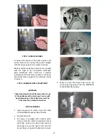
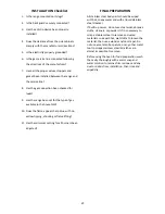
Page 23: ...ar sharp blue with no yellow tipping shooting or flame lifting 11 Has the minimum setting for all burners been adjusted FINAL PREPARATION All stainless steel body parts should be wiped with hot soapy water and with a liquid stainless steel cleanser If build up occurs do not use steel wool abrasive cloths cleaners or powders If it is necessary to scrape stainless steel to remove encrusted materials...

Page 24: ...rays in the vicinity of the appliance while cooking Do not sit or step on the oven door Do not use oven compartment for storage Use Care When Opening Door Let hot air or steam escape before removing or replacing food Do not heat unopened food containers Build up of pressure may cause container to burst and result in injury Keep oven vent ducts unobstructed Always place oven racks in desired locati...

Page 25: ...ner 4 Dual burner Power burner Model SURFACE COOKING SYMBOLS Burner position in this case front right burner Maximum temperature setting Recommended control knob position for burner ignition Minimum temperature setting Appliance with worktop gas valves alternative type ...

Page 26: ... the above procedure The dual power burner is composed by two burners inside and outside Each burner is activated by a separate control knob The two burners can be operated separately or together for maximum power To activate the power burner turn on the central burner first then turn on the external ring ATTENTION do not ignite burners if the black burner cap is not installed or not centred The f...

Page 27: ... while oven is hot do not let potholder contact hot heating element in oven Do Not Clean Door Gasket The door gasket is essential for a good seal Care should be taken not to rub damage or move the gasket Do Not Use Oven Cleaners No commercial oven cleaner or oven liner protective coating of any kind should be used in or around any part of the oven Clean Only Parts Listed in manual Before Self Clea...

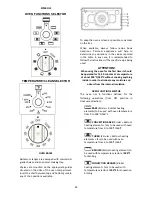
Page 28: ...using the oven for the first time it should be operated for 15 30 minutes at a temperature of about 500 F 260 C without cooking anything inside in order to eliminate any moisture and odours from the internal insulation OVEN FUNCTION SELECTOR The oven has 8 functions defined for the following operations from OFF position in clockwise direction BAKE Broiler Bottom heating elements to be used with ov...

Page 29: ...ors that activate when the oven is in operation for cooking or cleaning except in case of DEHYDRATE and PROOFING functions In stand by condition both selector in OFF position the cooling fan motors operate if oven temperature exceeds approximately 430 F 220 C and stop automatically when oven temperature drops below approximately 285 360 F 140 180 C FRONT INDICATOR LIGHTS This appliance is equipped...

Page 30: ...k of the oven moves heated air evenly around the oven The moving air provides even heat so foods can be placed on any rack level with consistent results and without having to rotate the pans Convection also enables cooking simultaneously on multiple racks Low shallow bake ware should be used with convection cooking This allows the heated air to properly move around the food Pans with high sides or...

Page 31: ...el RACK POSITIONS Large Main Oven One Rack Baking When baking on one rack best results are obtained in the bake mode see Bake When roasting a turkey or a large piece of meat convection bake may be used Rack 4 is the most appropriate rack Two Rack Baking Racks 4 and 2 are most appropriate when using the convection bake mode Round cake pans should be staggered on racks 4 and 2 Rectangular 9 x 13 cak...

Page 32: ...xed temperature of 140 F 60 C Level 2 with temperature selector set at 250 F internal oven setup fixed temperature of 170 F 77 C Level 3 with temperature selector set at 300 F internal oven setup fixed temperature of 220 F 105 C FOOD SAFETY The United States Department of Agriculture recommends to NOT keep food at temperatures between 40 F to 140 F for longer than 2 hours Cooking raw foods below 2...

Page 33: ... 4 slices 10 15 Soft pliable Cherries Wash and towel dry For fresh cherries remove pits 10 15 Pliable leathery chewy Orange peels and slices 1 4 slices of orange orange part of skin thinly peeled from oranges Peels 2 4 Slices 12 16 Orange peel dry and brittle Orange slices skins are dry and brittle fruit is slightly Pineapple rings Towel dried Canned 9 13 Fresh 8 12 Sott and pliable Strawberries W...

Page 34: ... the range Use metal or glass ceramic bake ware when browning casseroles main dishes or bread DO NOT use heat proof glass or pottery This type of glassware cannot withstand the intense heat of the broil element Broiling Using Meat Thermometer To more accurately define the preparation of thick steaks or chops at least 1 1 2 inches thick use a meat thermometer Insert the point of the thermometer int...

Page 35: ...to 25 min lb Small roasts take more minutes per pound reduce time by using Convection Bake PORK Loin Roast 3 Bake or Convection bake 325 20 to 25 min lb Cook until juices are clear POULTRY Boneless Skinless Chicken Breasts 2 Broiler or convection Broiler 500 F fixed temperature setting 20 to 25 minutes Cook until juices are clear Chicken Thighs 3 Broiler or convection Broiler 500 F fixed temperatu...

Page 36: ... AND SURROUNDING AREAS OPEN A NEARBY WINDOW FOR ADDITIONAL VENTILATION Door Lock When the CLEAN cycle starts the automatic door lock cycle begins Check the door to confirm that it is locked You can stop the self cleaning cycle by turning the function selector to the OFF posi tion The CLEANING light will turn off only after the oven has cooled below 500 260 C and the automatic door lock has complet...

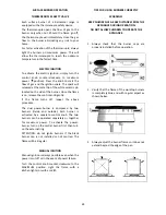
Page 37: ...th a soft sponge or wipe Alternatively use a soft sponge or cloth with a warm soap and water solution Never use abrasive powders or liquids Cleaning the burner caps lift the burner caps from the burner heads and wash them in a warm soap and water solution Dry thoroughly before using them again Before reinstalling them on the burner head check that the gas flow holes are not clogged with food resid...

Page 38: ...rical power to the oven Make sure the oven temperature has been selected Oven light is not working properly Replace or reinsert the light bulb if loose or defective Oven light stays on Check for obstruction in oven door Check to see if hinge is bent Cannot remove lens cover on light There may be soil build up around the lens cover Wipe lens cover area with a clean dry towel prior to attempting to ...

Page 39: ...NVECTION BROILER temperature knob positioned not at 500 F position over Tmax or under 450 F position select OFF position and then 500 F on temperature selector Or Wrong temperature knob selection for oven functions BAKE CONVECTION BAKE TURBO CONVECTION temperature knob positioned over Tmax 500 F position select OFF position and then the desired temperature under Tmax position on temperature select...

Page 40: ..._________________________________________________________ _______________________________________________________________ INSTALLER _______________________________________________________________ ________________________________________________________________ SERVICER _______________________________________________________________ ________________________________________________________________ ...

Page 41: ...41 BERTAZZONI SpA Via Palazzina 8 42016 Guastalla RE ITALY WWW BERTAZZONI ITALIA COM ...

Reviews: