5
USING THE INDUCTION HOB
HOB CONTROL KNOB
These knobs provide control of the ceramic hob's cooking zones.
The zone it controls is shown above eachknob. Turn the knob to the right to set the zone's operating power; the settings
range from a minimum of 1 to a maximum of 9. (fig.12)
The working power is shown by a display on the hob.
Heating accelerator
Each cooking zone is equipped with a heating accelerator.
This system allows the zone to be operated at peak power for a time proportional to the heating power selected.
To start the heating accelerator, turn the knob to the left, select setting "
A
" and then release. The letter "
A
" will appear on
the display on the hob.
You now have 3 seconds to select the heating setting of your choice. Once a setting between 1 and 9 has been selected,
"
A
" and the chosen setting will flash in alternation on the display. '
While the heating accelerator is in operation, the heating level can be increased at any time. The "full power" time will be
modified accordingly. If the power is reduced by turning the knob anticlockwise, option "
A
" is automatically deactivated.
Power Function
The power function allows the user to operate each heating zone continuously at the maximum power for a time of no
more than 10 minutes. This function can be used, for example, to bring a large amount of water to the boil in a hurry, or
to turn up the heat under meat.
Turn the knob clockwise and set heating level 9, then use the knob to set the "
P
" position and release il. "
P
" appears on
the corresponding zone display.
After 10 minutes, the power is reduced automatically, the knob returns to the 9 setting and the "P" disappears.
However, the power function can be turned
ott
at any time by reducing the heating level. .
When the power function is selected for one heating zone (e.g. the left front zone), the power absorbed by the second
zone (Ieft rear zone) might be reduced to supply the maximum available energy to the first zone.
Consequently, the power function takes priority over the heating accelerator.
If a pan is removed from the cooking zone while the power function is on, the function is switched off.
Holding Function
The holding function keeps the temperature of the bottoms of pans at about 65°C. This allows foods to be kept hot with
optimal energy consumption and to be heated gently. The holding function can be kept in operation for up to 2 hours.
The holding function is
and is indicated by the relevant symbols on the cooking zones.
HOB
ATTENTION:
Metal items such as cutlery or lids must never be placed on the surface of the hob since they may become hot.
Cooking zones (fig.13)
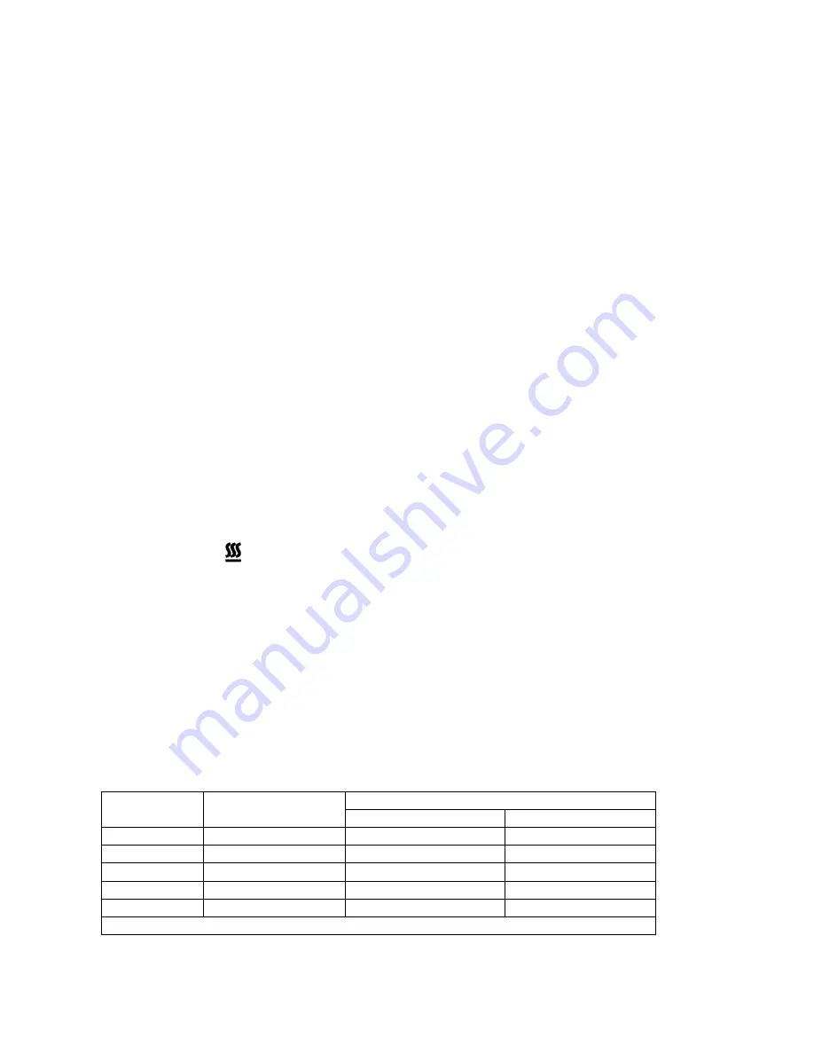
The appliance is equipped with 5 cooking zones having different diameters and powers. Their positions are clearly
marked by rings, while the heating power is only released in the area shown on the ceramic hob. The 5 cooking zones
are of HIGH-LlGHT type and start to heat up a few seconds after they are switched on. The heat level of each zone can
be regulated from the minimum to the maximum setting using the knobs on the front panel.
Underneath each cooking zone there is a coil called an
inductor,
supplied with power by an electronic system, which
generates a variable magnetic field. When a pan is placed inside this magnetic field, the highfrequency currents
concentrate directly on the bottom of the pan and produce the heat needed to cook the foods.
The 5 lights between the cooking zones come on when the temperature of one or more cooking zones exceeds 60° C..
The lights go out when the temperature drops to below about 60° C.
Zone number:
Zone diameter:
Power absorption
Normal operation:
With power function:
1 145
mm 1400W
1800W
2 210
mm 2300W
3200W
3 180
mm 1850W
2500W
4 210
mm 2300W
3200W
5 145
mm 1400W
1800W
Total power absorption 10000W
When the hob is used for the first time, it should be heated to its maximum temperature for long enough to bum off
any oily residues left by the manufacturing process, which might contaminate foods with unpleasant smells.
Summary of Contents for W90 IND MFE
Page 11: ...11 Fig 1 fig 3 ...
Page 12: ...12 Fig 4 Fig 5 Fig 6 Fig 7 Fig 8 Fig 9 ...
Page 13: ...13 Fig 10 Fig 11 Fig 12 Fig 13 Fig 14 Fig 15 ...
Page 14: ...14 Fig 16 Fig 17 Fig 18 Fig 19 Fig 20 ...
Page 15: ...15 ...
Page 16: ...16 Cod 310661 ...