9. Parameter Entries
FlowStar2 LB 514
76
9.1 Configuration of the Device
The device configuration is defined on the
Configuration
submenu.
On the measurement menu, select
Menu | Device | Configuration
.
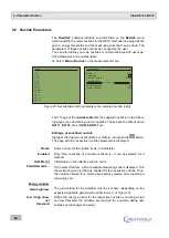
The first of three parameter pages is displayed.
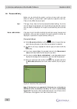
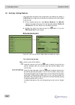
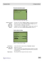
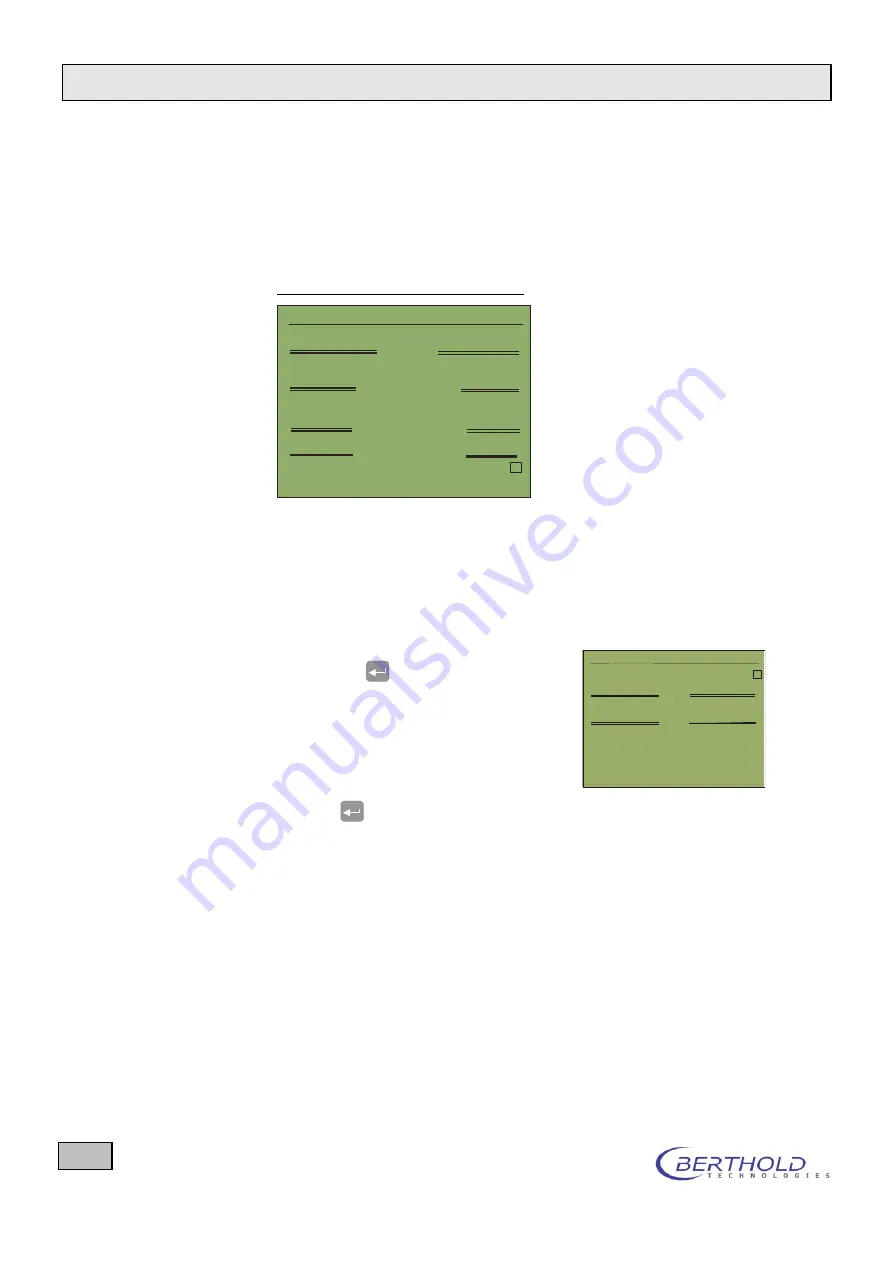
Configuration parameter page 1 / 3
CONFIGURATION
1 / 3
Display Configuration...
Backlight timeout [min]:
5
Adjust Display Contrast:
78
Control Voltage Det. A [V]:
1.300
Baudrate:
9600
Plug-In Card installed:
x
Analog Input Settings...
Control Voltage Det. B [V]:
1.300
LCD-Display
Electrical Parameters
Communication Port
External Analog Inputs
Figure 22: Configuration, parameter page 1/3
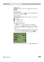
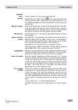
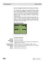
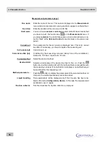
Display Configuration...
Here you can define which counting channels are to be displayed and how
the measurement diagrams should be arranged on the
Measurement
menu
.
Select
Display Configuration...
, and
push the
button to go to the param-
eter input.
Define on which page the radioactivity
signals and where channel 1 and chan-
nel 2 are to be displayed.
Highlight
1
st
page | Top Graphic
, and
push
.
In the following selection list (
Top Graphic
), select the channel that is
to be displayed on the first screen page at the top. You may select both
analog channels
Analog1
and
Analog2
and both radioactivity chan-
nels
Radio1
and
Radio2
and also the item
None
.
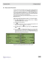
Proceed in the same manner with the other three screen positions.
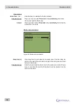
Define the scroll mode for the image display. You may choose
Jump
and
Scroll
.
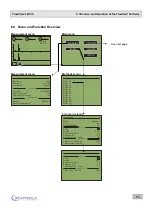
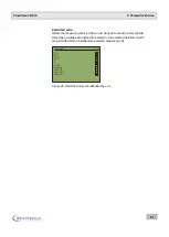
DISPLAY CONFIGURATION
1 / 1
Scroll cpm Values
x
Scroll Mode:
Jump
Upper Graph:
Radio 1
Lower Graph:
Radio 2
Upper Graph:
Analog 1
Lower Graph:
Analog 2
Page 1
Page 2

