Page 5
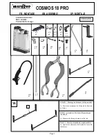
ETAPE 2 : Fixation du levier sur le balancier et
mise en place de la bielle
A : Mettre en place le levier n°3 coté bouchon à
l’extérieur du balancier n°1 en alignant la forme
et les trous.
2A
STEP 2 : Fix lever to the beam and assemble the
connecting rod
A : Place lever n°3 alongside beam n°1, on the
cap side of the tank, lining up the edges and the
holes as shown.
ETAPA 2 : Fijación de la palanca sobre el
balancín y montaje de la biela
A : Colocar la palanca n°3 lado tapón al exterior
del balancín alineando la forma y los huecos.
B : Insérer les 2 vis n°4 à travers le balancier.
B : Insert 2 screws n°4 into the beam.
B : Insertar los 2 tornillos n°4 a través del
balancín.
n°4
n°3
C : Insérer les rondelles n°5, les rondelles n°6 et
les écrous n°7 autour des vis n°4. Serrer les
écrous n°7 au maximum.
C : Place washers n°5, washers n°6 and nuts n°7
around the screws n°4. Tighten nuts n°7 to
maximum.
C : Insertar las arandelas n°5, las arandelas n°6 y
las tuercas n°7 en torno a los tornillos n°4.
Apretar las tuercas n°7 al máximo.
n°4
n°5
n°6
n°7
2B
2C
n°3
FR : GAUCHER
GB: LEFT HANDED USE
SP: ZURDO
n°3
n°1


