30
82.321-M - Pulvasol 1 and 2 / Pulvigne
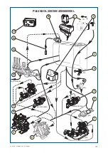
HYDRAULIC CIRCUIT OF THE PULVASOL SPRAYER
KEY FOR DIAGRAM
1
- Handwash tank of 15 or 18 litres (in option or of series according to model).
2
- Rinsing tank of 55 litres (optional).
3
- Main tank of 200, 300, 400, 600 or 800 litres.
4
- Drain valve (800).
5
- Suction filter group - drain valve (200/300/400/600) without rinsing tank (for BP
105 pump).
6
- Suction filter (800).
7
- Suction filter group - drain valve (600) with rinsing tank (for BP 105 pump).
8
- BP 105 pump (105 litres - 20 bar).
9
- BP 60 pump (60 litres - 20 bar).
10
- Suction filter group - drain valve (200/300/400/600) without rinsing tank (for BP
60 pump).
11
- Suction filter group - drain valve (600) with rinsing tank (for BP 60 pump).
12
- Manual block: 3 distributors, 1 main valve, 1/4 turn, 1 regulator (with or without
flowmeter).
13
- Tank return pipework for hydraulic stirring (for case without hydro-injector).
14
- Filling pipe with strainer (for case with hydro-injector).
15
- Control box "
Berjust 2
" (flowmeter).
16
- Hydro-injector (optional).
PULVASOL 200/300/400/600/800 L
Summary of Contents for PULVASOL 200
Page 2: ...2 82 321 M Pulvasol 1 and 2 Pulvigne...
Page 4: ...4 82 321 M Pulvasol 1 and 2 Pulvigne...
Page 6: ...6 82 321 M Pulvasol 1 and 2 Pulvigne...
Page 10: ...10 82 321 M Pulvasol 1 and 2 Pulvigne...
Page 15: ...15 82 321 M Pulvasol 1 and 2 Pulvigne 3 1 2 2 1 2 3 2 1 3 1...
Page 17: ...17 82 321 M Pulvasol 1 and 2 Pulvigne 1 2 3 4 5 4 3 2 1 4 5...
Page 27: ...27 82 321 M Pulvasol 1 and 2 Pulvigne B P 60 20 B P 105 20 13 14...
Page 29: ...29 82 321 M Pulvasol 1 and 2 Pulvigne MAINTENANCE DIAGRAMS...


