Service and Maintenance for Cylindrical Locks
5–18
W Series Service Manual
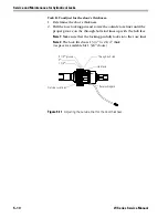
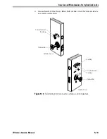
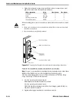
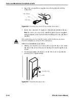
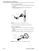
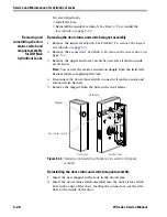
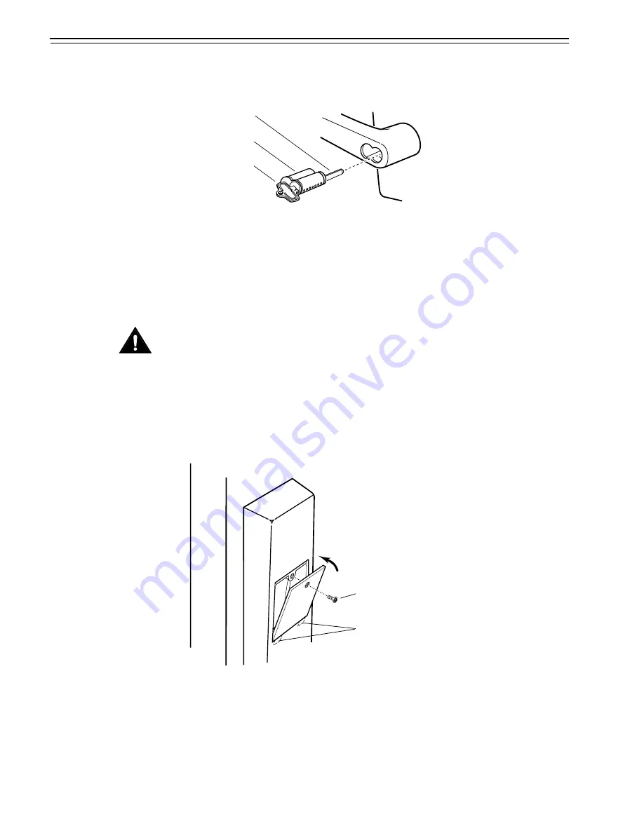
4. Insert the core and throw member into the lever/knob with the
control key.
5. Rotate the control key 15 degrees to the left and withdraw the key.
Note:
For 6-pin core users only
, install the plastic spacer (supplied
with permanent cores) instead of the blocking plate onto the throw
member.
Caution
The control key can be used to remove cores and to access doors.
Provide adequate security for the control key.
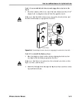
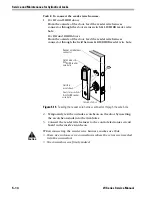
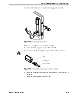
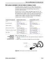
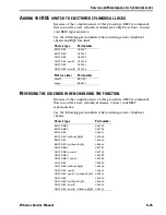
Task J. To reinstall the access door:
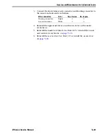
1.
Making sure that the access door does not pinch any wires
, insert
the tabs of the access door into its mating slots and swing the door
closed.
2. Use the appropriate bit driver to secure the access door with the
security screw. Tighten firmly.
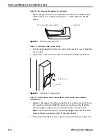
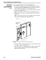
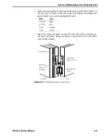
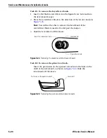
Figure 5.20
Reinstalling the core and throw member (lever shown)
Core
Control key
Throw member
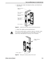
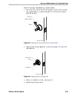
Figure 5.21
Reinstalling the access door
Security screw
Tabs
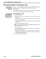
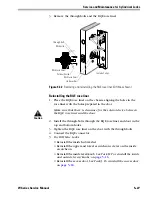
Summary of Contents for 34HW
Page 1: ......
Page 6: ...Contents vi W Series Service Manual...
Page 38: ...IDH Max Locks Functions and Parts 2 24 W Series Service Manual...
Page 54: ...Electrified Locks Functions and Parts 3 16 W Series Service Manual...
Page 140: ...Service and Maintenance for Cylindrical Locks 5 30 W Series Service Manual...
Page 158: ...Additional Service and Maintenance for IDH Max Locks 6 18 W Series Service Manual...
Page 162: ...Glossary A 4 W Series Service Manual...
Page 164: ...Installation Instructions B 2 W Series Service Manual...

