Additional Service and Maintenance for IDH Max Locks
6–2
W Series Service Manual
R
EPLACING
WIRE
HARNESSES
Removing and
reinstalling the
sensor and solenoid
wire harness
Removing the sensor and solenoid wire harness
1. Remove the core and throw member. For mortise instructions, see
. For cylindrical
instructions, see
Task A. To remove the core and throw member:
2. Use the appropriate bit driver to remove the security screw from the
access door. Open the access door and remove it from the inside
escutcheon.
3. Remove the inside lever/knob. For mortise instructions,
see
Task B. To remove the inside and outside levers/knobs:
. For cylindrical instructions, see
.
4. Remove the upper and lower escutcheon screws from the inside
escutcheon. Pull the inside escutcheon away from the door enough
to expose the control electronics circuit board.
Note:
You can let the inside escutcheon dangle from the field wire
harness while completing this task.
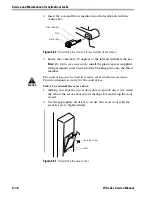
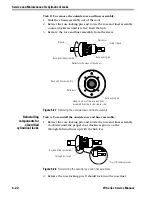
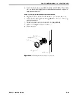
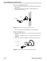
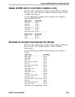
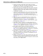
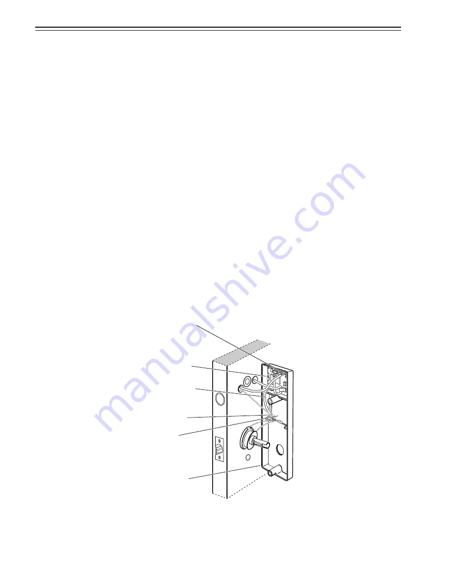
5. Disconnect the three sensor connections and the solenoid
connection.
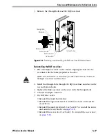
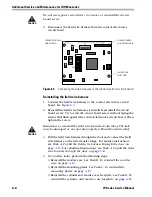
6. Disconnect the sensor and solenoid wire harness from the control
electronics circuit board.
Figure 6.1
Disconnecting and connecting the reader wire harness (cylindrical lock
shown)
Inside of door
Reader wire harness
connector
Sensor wires and
solenoid wire
Inside escutcheon
Large opening
Solenoid and sensor
wire harness
Control electronics
circuit board
Summary of Contents for 34HW
Page 1: ......
Page 6: ...Contents vi W Series Service Manual...
Page 38: ...IDH Max Locks Functions and Parts 2 24 W Series Service Manual...
Page 54: ...Electrified Locks Functions and Parts 3 16 W Series Service Manual...
Page 140: ...Service and Maintenance for Cylindrical Locks 5 30 W Series Service Manual...
Page 158: ...Additional Service and Maintenance for IDH Max Locks 6 18 W Series Service Manual...
Page 162: ...Glossary A 4 W Series Service Manual...
Page 164: ...Installation Instructions B 2 W Series Service Manual...

