BEST ACCESS SYSTEMS
Indianapolis, Indiana
Electrical requirements
The following table describes the voltage and current specifications for
the mortise lock, RQE switch, and door monitoring switch.
Parts List
The following table describes the parts illustrated in Figure 37. You may
substitute most components with equivalent parts.
Unit
Voltage
Current
34H–37HW
24 volts AC or DC 0.75 amp
RQE switch rating
30 volts DC
0.1 amp max.
Door monitoring
switch
30 volts DC max.
0.5 amp max./7.5
watts max.
Part number
Description
8W599
Transformer—24 volt AC, 40 volt-amps. See the
examples under Installation Hints on the reverse side.
8WTCM
Temperature control module
8WDTL
Door transfer loop. You may substitute this with a
power transfer hinge.
8WMOV
Metal oxide varistor
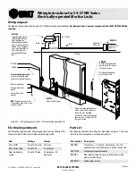
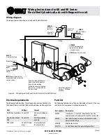
Wiring diagram
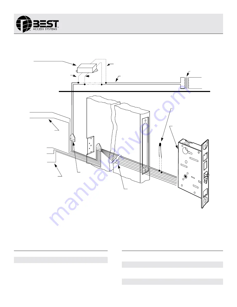
The diagram below shows how to wire 34–37HW electrically-operated locks.
Dashed wire lines represent components that MAY OR MAY NOT be
required.
Figure 37—Wiring diagram for the 34–37H electrically-operated lock
8WTCM
Supplied with electri-
cally-locked (EL) func-
tions (optional on
electrically-unlocked)
and is used to minimize
knob or lever tempera-
ture. Locate within 20
feet of the lock. Use
only one 8WTCM per
lock.
White
White
8WMOV
Use this component on
power wires to reduce
electrical surges.
Run wires through the door or
mount wires to the door sur-
face with wire molding.
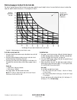
To find the correct wire gauge
for wire runs, see Figure 38 on
the reverse side.
RQE
(Request-to-exit) wires
are normally used with access
control systems.
8WDTL
Door transfer loop
Door monitoring switch
wires are normally used
with access control systems.
Black
Red
White
Blue
Ceiling
Brown (common)
Orange (Normally
open)
Green (Normally
closed)
24 volts AC
60 Hz. out
120 volts AC
60 Hz. in
8W599
Electrically-operated
mortise lock case.
(Over)
Wiring Instructions for 34–37HW Series
Electrically-operated Mortise Locks
T61993/Rev – 18XXXXX ER7991-19 June 2000
Summary of Contents for 34HW
Page 1: ......
Page 6: ...Contents vi W Series Service Manual...
Page 38: ...IDH Max Locks Functions and Parts 2 24 W Series Service Manual...
Page 54: ...Electrified Locks Functions and Parts 3 16 W Series Service Manual...
Page 140: ...Service and Maintenance for Cylindrical Locks 5 30 W Series Service Manual...
Page 158: ...Additional Service and Maintenance for IDH Max Locks 6 18 W Series Service Manual...
Page 162: ...Glossary A 4 W Series Service Manual...
Page 164: ...Installation Instructions B 2 W Series Service Manual...

