BEST ACCESS SYSTEMS
Indianapolis, Indiana
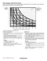
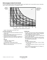
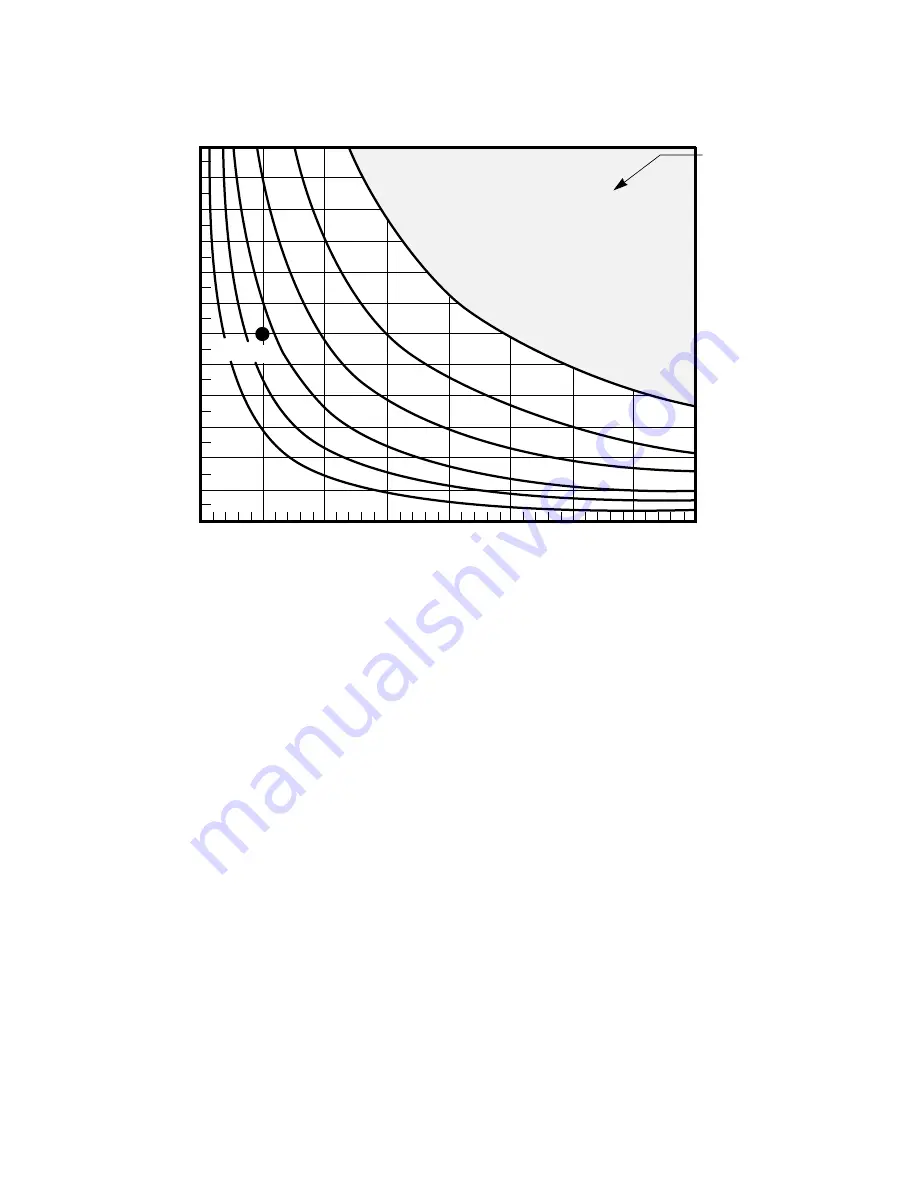
Minimum gauge wire chart for lock circuits
The chart in Figure 38 helps you find the minimum wire gauge needed for a specific length wire run. It assumes that the lock circuit is made of two
conductor cable. The chart also factors in a 15% voltage loss at 24 volts.
Figure 38—Minimum gauge wire chart for lock circuits
10 AWG wire
12 AWG wire
14 AWG wire
16 AWG wire
18 AWG wire
20 AWG wire
Example
Do not use this
chart for any plots
made to this
shaded area.
1.500
1.375
1.250
1.125
1.000
.875
.750
.625
.500
.375
.250
.125
0
500'
1000'
1500'
2000'
2500'
3000'
3500'
4000'
Maximum
lock current
(in amps)
Total footage of two conductor cable for lock circuit (in feet)
To find the correct gauge wire:
1 Determine the maximum lock current and find that value on the left
side of the chart.
2 Determine the total footage of cable to be used in the lock circuit
and find that value at the bottom of the chart.
3 Locate the intersection of current and footage. The line above or to
the right of the intersection shows what minimum gauge wire you
need.
Example
▲
Lock current: 0.750 amp maximum
▲
Total wire run: 500 feet
Wire gauge needed: 16 AWG two conductor cable
Note:
For 12 volt locks, double the maximum lock current, then use
that value on the left side of the chart.
Installation hints
1 Wire gauge (or size) determines how efficiently the lock will operate.
Consider wire gauge before installation. To find the recommended
minimum wire gauge for all wire runs, see Figure 38.
2 Use wire of 20 AWG (gauge) or larger. We do not recommend using a
smaller wire gauge than 20 AWG.
3 When wiring two or more locks to a single power supply, make sure
that the power rating of the power supply is 1
½
times greater than
the sum of the lock’s power requirement.
Example
For two locks powered by one supply:
▲
Lock 1 (30H) is rated at 24 volts, 0.75 amps—24 volts
×
0.75 amps
= 18 volt-amps
▲
Lock 2 (30H) is rated at 24 volts, 0.75 amps—24 volts
×
0.75 amps
= 18 volt-amps
Choose a transformer with a rating of at least: (18 volt-amps + 18
volt-amps)
×
1
½
= 54 volt-amps
T61993/Rev – 18XXXXX ER7991-19 June 2000
Summary of Contents for 34HW
Page 1: ......
Page 6: ...Contents vi W Series Service Manual...
Page 38: ...IDH Max Locks Functions and Parts 2 24 W Series Service Manual...
Page 54: ...Electrified Locks Functions and Parts 3 16 W Series Service Manual...
Page 140: ...Service and Maintenance for Cylindrical Locks 5 30 W Series Service Manual...
Page 158: ...Additional Service and Maintenance for IDH Max Locks 6 18 W Series Service Manual...
Page 162: ...Glossary A 4 W Series Service Manual...
Page 164: ...Installation Instructions B 2 W Series Service Manual...

