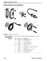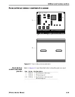
Electrified Locks Functions and Parts
3–6
W Series Service Manual
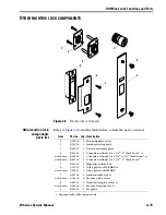
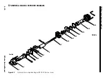
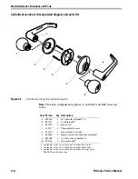
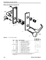
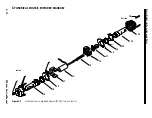
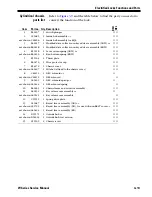
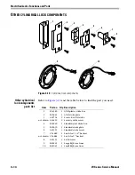
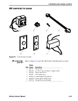
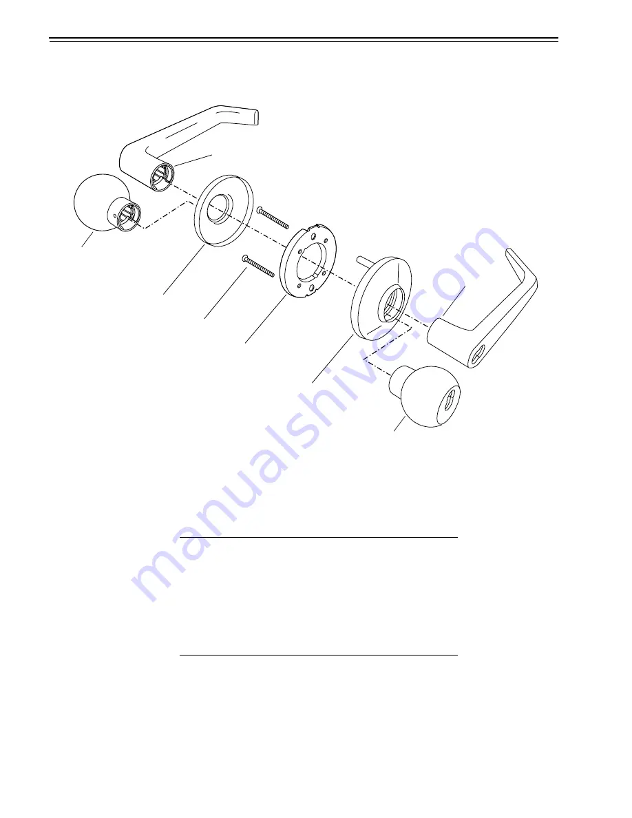
Cylindrical sectional trim exploded diagram and parts list
Note:
This trim configuration applies to both DEL and DEU function
locks.
Figure 3.4
Cylindrical sectional trim exploded diagram
1
2
3
4
1
6
5
6
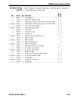
Item Part no.
Qty. Description
1
(1)
E55169
B54707
1
1
#15 plain lever handle
a
or
#4 plain knob
b
a. See the
9K Series Service Manual
for other lever styles.
b. See the
8K Series Service Manual
for other knob styles.
2
B55007
1
Large rose
c
c. See the
9K Series Service Manual
for other rose trim styles.
The 8KW uses 9K rose trim.
3
A55557
2
Through-bolt screw
4
C55555
1
Large inside rose liner
c
5
B55601
1
Large outside rose and liner assembly
c
6
(6)
E55168
B54704
1
1
#15 keyed lever handle
a
or
#4 keyed knob
b
Summary of Contents for 34HW
Page 1: ......
Page 6: ...Contents vi W Series Service Manual...
Page 38: ...IDH Max Locks Functions and Parts 2 24 W Series Service Manual...
Page 54: ...Electrified Locks Functions and Parts 3 16 W Series Service Manual...
Page 140: ...Service and Maintenance for Cylindrical Locks 5 30 W Series Service Manual...
Page 158: ...Additional Service and Maintenance for IDH Max Locks 6 18 W Series Service Manual...
Page 162: ...Glossary A 4 W Series Service Manual...
Page 164: ...Installation Instructions B 2 W Series Service Manual...

