Service and Maintenance for Mortise Locks
4–32
W Series Service Manual
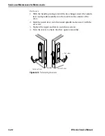
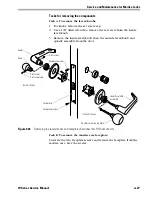
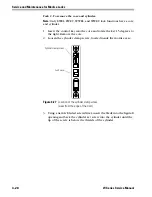
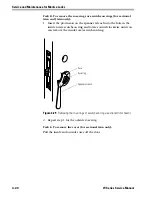
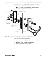
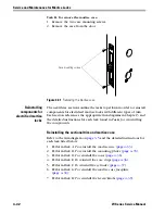
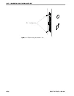
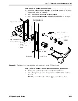
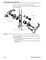
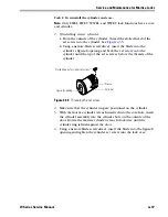
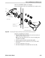
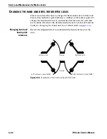
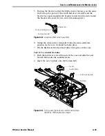
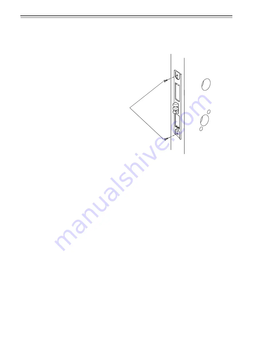
Task H. To remove the mortise case:
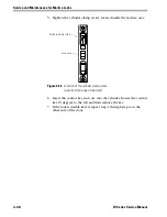
1. Remove the two case mounting screws.
2. Remove the case from the door.
Reinstalling
components for
electrified mortise
locks
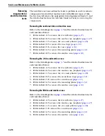
The next three sections outline the tasks to perform in order to reinstall
components for electrified mortise locks with different types of trim.
Each section references the appropriate trim diagrams in Chapter 3 and
the detailed instructions for each task found in
Tasks for reinstalling
the components
.
Reinstalling the sectional trim and mortise case
Refer to the trim diagram on
and the detailed instructions for
each task listed below.
1. Perform
Task A.
To reinstall the mortise case
(
2. Perform
Task B.
To reinstall the mounting plates
3. Perform
Task D.
To reinstall the roses
(
4. Perform
Task E.
To reinstall the rose rings
(
5. Perform
Task F.
To reinstall the cylinder
6. Perform
Task G.
To reinstall the mortise case faceplate
7. Perform
Task H.
To reinstall the levers/knobs
(
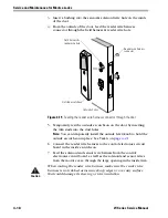
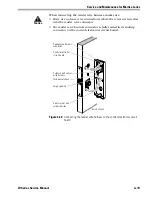
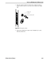
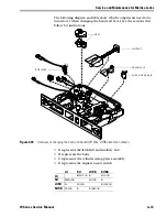
Figure 4.31
Removing the mortise case
Case mounting screws
Summary of Contents for 34HW
Page 1: ......
Page 6: ...Contents vi W Series Service Manual...
Page 38: ...IDH Max Locks Functions and Parts 2 24 W Series Service Manual...
Page 54: ...Electrified Locks Functions and Parts 3 16 W Series Service Manual...
Page 140: ...Service and Maintenance for Cylindrical Locks 5 30 W Series Service Manual...
Page 158: ...Additional Service and Maintenance for IDH Max Locks 6 18 W Series Service Manual...
Page 162: ...Glossary A 4 W Series Service Manual...
Page 164: ...Installation Instructions B 2 W Series Service Manual...

