Service and Maintenance for Mortise Locks
W Series Service Manual
4–45
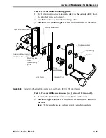
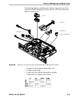
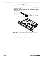
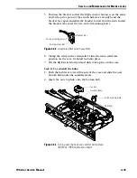
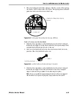
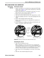
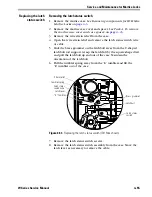
5. Position the bracket so that the RQE actuator button is on the same
end as the pivot point of the switch hub lever. Gently bend the
bracket feet apart and slide the bracket forward on the switch until
the bracket tabs enter the two switch mounting holes.
6. Clamp the wires in the strain relief. Slide the strain relief into
position on the case. It should lock into place.
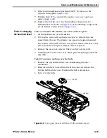
7. Tilt the RQE switch forward and slide it into place in the case.
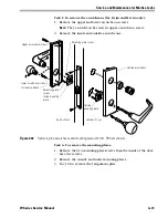
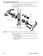
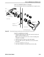
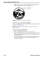
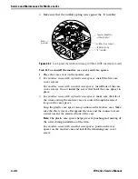
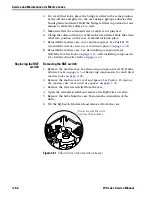
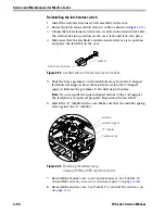
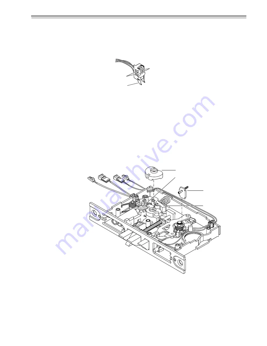
Task D. To reinstall the hubs:
1. Push the hub lever toward the side of the case and slide the now
bottom hub under the auxiliary levers.
2. Insert the now top hub onto the bottom hub.
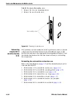
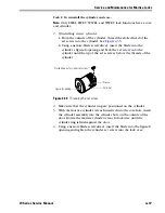
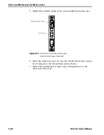
Figure 4.42
Assembled RQE switch assembly
Switch bracket feet
Switch mounting holes
Bracket tabs
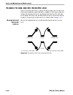
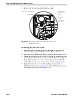
Figure 4.43
Turning over the hubs and cylinder clamp plate
(IDH Max, LHRB orientation shown)
Top hub
Cylinder clamp plate
Hub lever
Auxiliary levers
Summary of Contents for 34HW
Page 1: ......
Page 6: ...Contents vi W Series Service Manual...
Page 38: ...IDH Max Locks Functions and Parts 2 24 W Series Service Manual...
Page 54: ...Electrified Locks Functions and Parts 3 16 W Series Service Manual...
Page 140: ...Service and Maintenance for Cylindrical Locks 5 30 W Series Service Manual...
Page 158: ...Additional Service and Maintenance for IDH Max Locks 6 18 W Series Service Manual...
Page 162: ...Glossary A 4 W Series Service Manual...
Page 164: ...Installation Instructions B 2 W Series Service Manual...

