Servicing Standard Mortise Case Parts
6–6
B.A.S.I.S. V Service Manual
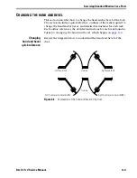
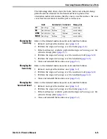
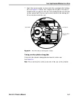
Tasks for changing
the hand and bevel
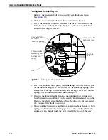
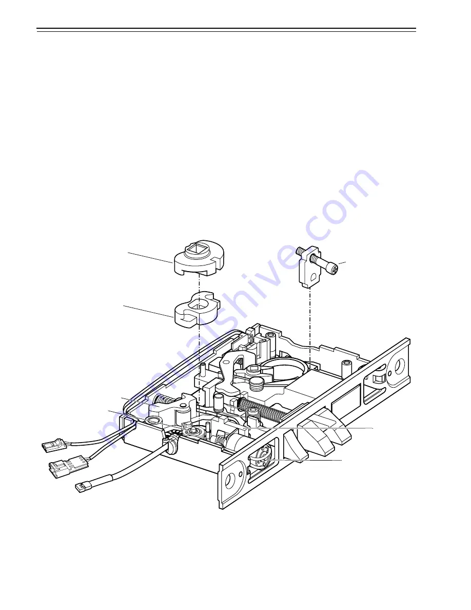
Turning over the hubs
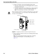
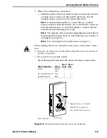
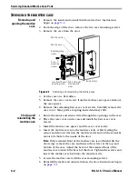
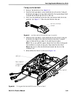
1. Rotate the locking bar and motor module. See
Figure 6.4
and
Figure 6.5
. Remove the locking bar from the case.
2. Remove the top hub from the case, maintaining the hub’s
orientation.
3. Push the hub lever toward the side of the case and remove the
bottom hub from the case. Maintain the hub’s orientation.
4. Turn over the hubs.
5. Push the hub lever toward the side of the case and slide the now
bottom hub under the auxiliary levers.
6. Insert the now top hub onto the bottom hub.
Note:
The inside hub is silver-colored. It is always on the side of the
case that faces the inside of the door. The outside hub is gold-
colored. It is always on the side of the case that faces the outside of
the door.
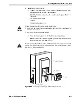
Figure 6.4
Turning over the hubs and cylinder clamp plate (FV function, LH case shown)
Inside hub
Hub lever
Outside hub
Cylinder clamp plate
Motor module
Locking bar
Auxiliary levers
Summary of Contents for B.A.S.I.S. V
Page 1: ...SERVICE MANUAL SERVICE MANUAL ...
Page 16: ...Figures xvi B A S I S V Service Manual ...
Page 48: ...Standard Functions and Parts 2 24 B A S I S V Service Manual ...
Page 66: ...Exit Hardware Trim Functions and Parts 3 18 B A S I S V Service Manual ...
Page 78: ...Shared Standard and Exit Hardware Trim Parts 4 12 B A S I S V Service Manual ...
Page 114: ...Servicing Standard Mortise Case Parts 6 20 B A S I S V Service Manual ...
Page 206: ...Servicing Exit Hardware Trim Escutcheon Parts 10 32 B A S I S V Service Manual ...
Page 238: ...Troubleshooting 12 12 B A S I S V Service Manual ...
Page 242: ...Lock History Event Types A 4 B A S I S V Service Manual ...
Page 244: ...Installation Instructions B 2 B A S I S V Service Manual ...

