Servicing Cylindrical Parts
B.A.S.I.S. V Service Manual
7–11
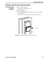
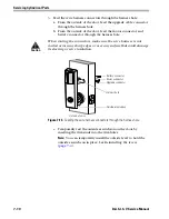
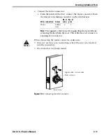
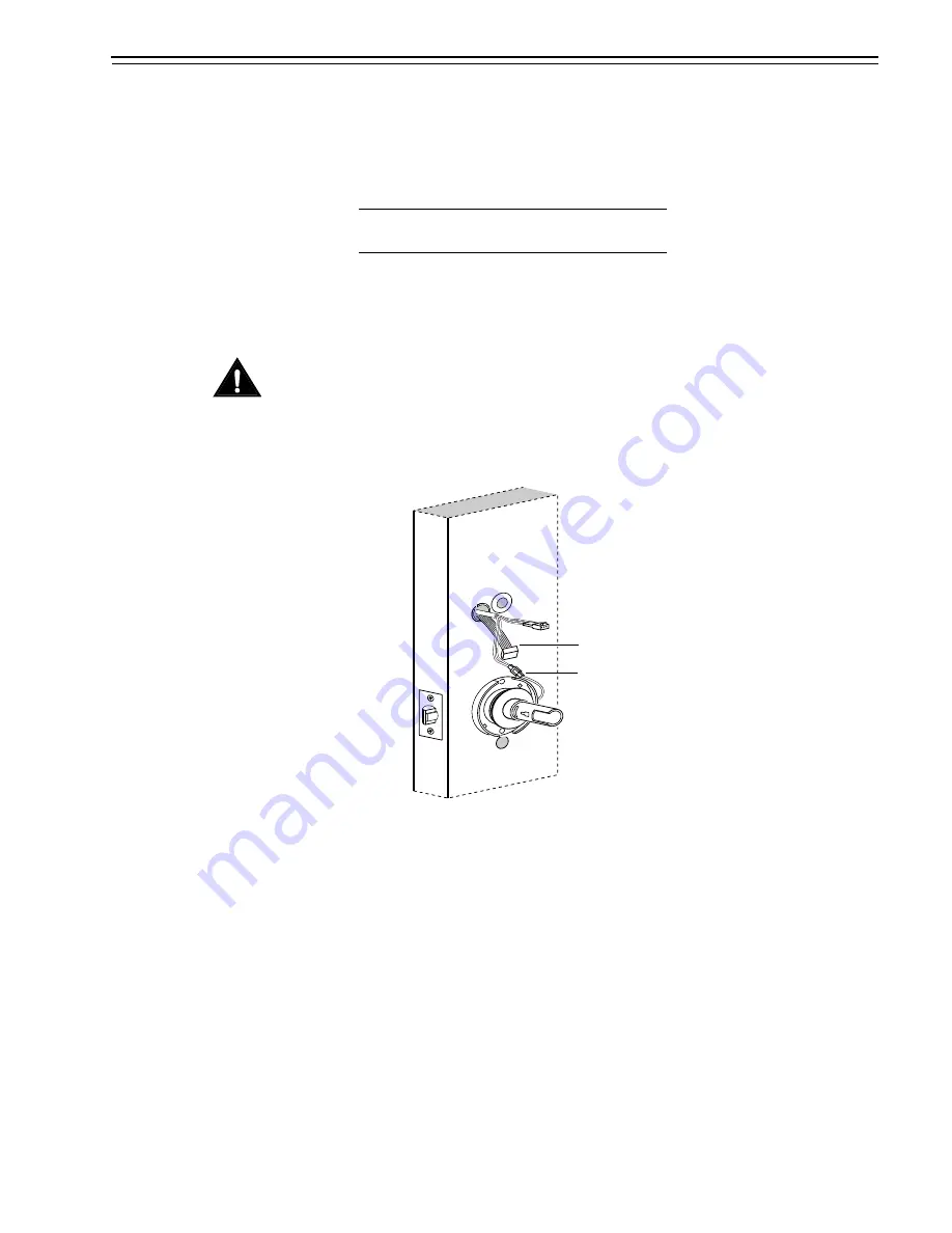
4. Connect the motor connector:
a. From the inside of the door, connect the motor connector from
the chassis to its mating connector on the wire harness.
Note:
The upgrade cable is used for upgrading the lock without
removing the lock from the door. This cable does not connect to
a mating lock connector.
Caution
When connecting the motor connector, make sure:
■
there are no loose wire connections where the wires are inserted
into the connectors
■
the connectors are firmly mated.
Wire connection Colors
No. of
wires
No. of
pins
Motor
Yellow
Gray
2
2
Figure 7.14
Connecting the motor connector
Inside of door
Motor connector
Upgrade cable – not connected
Summary of Contents for B.A.S.I.S. V
Page 1: ...SERVICE MANUAL SERVICE MANUAL ...
Page 16: ...Figures xvi B A S I S V Service Manual ...
Page 48: ...Standard Functions and Parts 2 24 B A S I S V Service Manual ...
Page 66: ...Exit Hardware Trim Functions and Parts 3 18 B A S I S V Service Manual ...
Page 78: ...Shared Standard and Exit Hardware Trim Parts 4 12 B A S I S V Service Manual ...
Page 114: ...Servicing Standard Mortise Case Parts 6 20 B A S I S V Service Manual ...
Page 206: ...Servicing Exit Hardware Trim Escutcheon Parts 10 32 B A S I S V Service Manual ...
Page 238: ...Troubleshooting 12 12 B A S I S V Service Manual ...
Page 242: ...Lock History Event Types A 4 B A S I S V Service Manual ...
Page 244: ...Installation Instructions B 2 B A S I S V Service Manual ...

