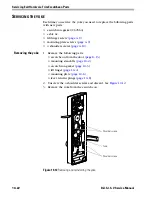
Servicing Exit Hardware Trim Escutcheon Parts
B.A.S.I.S. V Service Manual
10–25
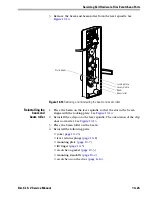
3. Remove the beam and beam roller from the lever spindle. See
Figure 10.14
.
Reinstalling the
beam and
beam roller
1. Place the beam on the lever spindle so that the slot in the beam
aligns with the locking plate. See
Figure 10.14
.
2. Reinstall the c-clip onto the lever spindle. The orientation of the clip
does not matter. See
Figure 10.13
.
3. Place the beam roller on the beam.
4. Reinstall the following parts:
■
yoke (
page 10–23
)
■
lever return springs (
page 10–8
)
■
mounting plate (
page 10–7
)
■
lift finger (
page 10–5
)
■
escutcheon gasket (
page 10–3
)
■
mounting standoffs (
page 10–2
)
■
escutcheon on the door (
page 8–14
).
Figure 10.14
Removing and reinstalling the beam and beam roller
Beam
Slot in beam
Beam roller
Lever spindle
Locking plate
Summary of Contents for B.A.S.I.S. V
Page 1: ...SERVICE MANUAL SERVICE MANUAL ...
Page 16: ...Figures xvi B A S I S V Service Manual ...
Page 48: ...Standard Functions and Parts 2 24 B A S I S V Service Manual ...
Page 66: ...Exit Hardware Trim Functions and Parts 3 18 B A S I S V Service Manual ...
Page 78: ...Shared Standard and Exit Hardware Trim Parts 4 12 B A S I S V Service Manual ...
Page 114: ...Servicing Standard Mortise Case Parts 6 20 B A S I S V Service Manual ...
Page 206: ...Servicing Exit Hardware Trim Escutcheon Parts 10 32 B A S I S V Service Manual ...
Page 238: ...Troubleshooting 12 12 B A S I S V Service Manual ...
Page 242: ...Lock History Event Types A 4 B A S I S V Service Manual ...
Page 244: ...Installation Instructions B 2 B A S I S V Service Manual ...


