Troubleshooting
B.A.S.I.S. V Service Manual
12–3
E
NABLING
COMMUNICATIONS
WITHOUT
A
CARD
OR
PASSWORD
If the card or password is lost or unavailable, you can enable
communications by pressing the password override button on the
control electronics board, which is located on the inside of the outside
escutcheon. This procedure will not affect the user database, history, or
lock configuration.
Caution
B
efore you handle the control electronics board or any component
on the control electronics board, make sure that you are properly
grounded using an electrostatic discharge (ESD) protection kit.
Touching the control electronics board without proper grounding can
damage sensitive electronic components—even if you don’t notice
any static discharge.
1.
For standard locks,
remove the inside and outside escutcheons
from the door. For mortise lock instructions, see
page 5–3
. For
cylindrical lock instructions, see
page 7–5
.
For exit hardware trim,
remove the B.A.S.I.S. escutcheon from the
door. See
page 8–13
.
2.
For standard locks,
peel back the lower edge of the gasket from the
outside escutcheon to expose the lower portion of the control
electronics board.
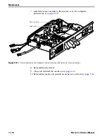
For exit hardware trim,
remove the following parts from the
escutcheon to expose the control electronics board:
■
mounting standoffs (
page 10–2
)
■
escutcheon gasket (
page 10–3
)
■
lift finger (
page 10–4
)
■
mounting plate (
page 10–6
).
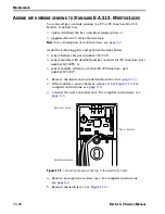
3. Connect the PDA to the lock:
a. Connect the serial cable to the PDA.
b. Connect the serial cable to the programming cable.
c. Connect the programming cable to the lock’s communication
port. The connector snaps into place.
Note 1:
For standard locks, the communication port is located in
the bottom of the outside escutcheon.
Note 2:
When the B.A.S.I.S. escutcheon for exit hardware trim has
been removed from the door, the communication port is located
on the end of the primary harness.
Summary of Contents for B.A.S.I.S. V
Page 1: ...SERVICE MANUAL SERVICE MANUAL ...
Page 16: ...Figures xvi B A S I S V Service Manual ...
Page 48: ...Standard Functions and Parts 2 24 B A S I S V Service Manual ...
Page 66: ...Exit Hardware Trim Functions and Parts 3 18 B A S I S V Service Manual ...
Page 78: ...Shared Standard and Exit Hardware Trim Parts 4 12 B A S I S V Service Manual ...
Page 114: ...Servicing Standard Mortise Case Parts 6 20 B A S I S V Service Manual ...
Page 206: ...Servicing Exit Hardware Trim Escutcheon Parts 10 32 B A S I S V Service Manual ...
Page 238: ...Troubleshooting 12 12 B A S I S V Service Manual ...
Page 242: ...Lock History Event Types A 4 B A S I S V Service Manual ...
Page 244: ...Installation Instructions B 2 B A S I S V Service Manual ...


